
| 概要 | |
|---|---|
|
ファイル: \examples\Processing\Trigger\mE4VD4-CL\Line\TrgPortLineRebuild_mE4VD4CL.va |
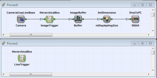 |
|
デフォルトプラットフォーム: mE4VD4-CL |
|
|
簡単な説明 VisualAppletsオペレーターのTrgPortLineは、VisualAppletsのオペレーターライブラリに含まれる他の信号処理オペレーターを使用して再構築されています。 この再構築により、カスタムのトリガー機能を実装でき、VisualAppletsにおける多数の信号処理オペレーターの使用方法を確認できます。 |
|
オペレーターTrgPortLineは、幅広いラインスキャン・トリガー機能を提供する複雑なVisualAppletsオペレーターです。アプリケーションによっては、カスタムの信号処理のためにこのオペレーターの動作を変更する必要が生じる場合があります。
この例では、他のVisualApplets信号処理オペレーターを使用したTrgPortLineオペレーターの再構築について説明します。これにより、お客様の要件に合わせて機能を適応・変更することが可能です。 実装は高度ですが理解しやすいものとなっています。この実装の複雑なパラメータ設定を簡素化するため、次の換算表を使用して、TrgPortLineのパラメータ名に基づいて新しいデザインのパラメータを計算できます。
| 名前 | YOffset |
|---|---|
| Default | 0 |
Device1_Process0_ImageTrigger_ImageHeight_Width = YHeight - YOffset Device1_Process0_ImageTrigger_ImageTriggerDelay_Delay_Delay = YHeight + YOffset |
|
| 名前 | YHeight |
|---|---|
| Default | 1024 |
Device1_Process0_ImageTrigger_ImageHeight_Width = YHeight - YOffset Device1_Process0_ImageTrigger_ImageTriggerDelay_Delay_Delay = YHeight + YOffset |
|
| 名前 | LineTriggerMode |
|---|---|
| Default | GrabberControlled |
Device1_Process1_LineTrigger_LineTriggerMode_Select = 3 if GrabberController 0,1 or 2 if Extern_Trigger For Extern_Trigger, the correct value is defined by the shaft encoder settings. The other modes available by TrgPortLine are not supported. |
|
| 名前 | ExsyncEnable |
|---|---|
| Default | OFF |
Device1_Process1_LineTrigger_Exsync_ExsyncEnable_Select = 1 if ON 0 if OFF |
|
| 名前 | LineTrgInSourceA |
|---|---|
| Default | 0 |
Device1_Process1_LineTrigger_TraceA_Input_Select = LineTrgInSourceA |
|
| 名前 | LineTrgInSourceB |
|---|---|
| Default | 1 |
Device1_Process1_LineTrigger_TraceB_Input_Select = LineTrgInSourceB |
|
| 名前 | EncoderABMode |
|---|---|
| Default | Signal_A_Only |
Device1_Process1_LineTrigger_LineTriggerMode_Select = 3 if LineTriggermode == GrabberControlled 0 if EncoderABMode == Signal_A_Only 1 else Device1_Process1_LineTrigger_ShaftEncoder_Mode = Mode1X if EncoderABMode == Signal_AB_Filter Mode2X if EncoderABMode == Signal_ABx2_Filter Mode4X if EncoderABMode == Signal_ABx4_Filter |
|
| 名前 | EncoderABLead |
|---|---|
| Default | Signal_AB |
Device1_Process1_LineTrigger_ShaftEncoder_LeadingTrace = A if EncoderABLead == Signal_AB B else |
|
| 名前 | LineTrgInPolarity |
|---|---|
| Default | LowActive |
Device1_Process1_LineTrigger_TraceA_Polarity_Invert = Invert if LineTrgInPolarity = LowActive NotInvert else |
|
| 名前 | LineTrgInPolarity |
|---|---|
| Default | LowActive |
Device1_Process1_LineTrigger_TraceA_Polarity_Invert = Invert if LineTrgInPolarity = LowActive NotInvert else Device1_Process1_LineTrigger_TraceB_Polarity_Invert = Invert if LineTrgInPolarity = LowActive NotInvert else |
|
| 名前 | LineTrgDownscaler |
|---|---|
| Default | 1 |
Device1_Process1_LineTrigger_Downscale_Donwscale = LineTrgDownscaler |
|
| 名前 | LineTrgPhase |
|---|---|
| Default | 1 |
Device1_Process1_LineTrigger_Downscale_SelectecPulse = LineTrgPhase |
|
| 名前 | ExsyncPeriod |
|---|---|
| Default | 100µs |
Device1_Process1_LineTrigger_Generate_Period = ExsyncPeriod / TClk |
|
| 名前 | Exsync2Delay | |||
|---|---|---|---|---|
| Default | 0µs | |||
Device1_Process1_LineTrigger_Exsync_Exsync2_Delay = Exsync2Delay / TClk
|
||||
![[注]](../common/images/admon/note.png)
| 名前 | ExsyncPolarity |
|---|---|
| Default | LowActive |
Device1_Process1_LineTrigger_Exsync_OutputPolarity_Polarity = Invert if ExsyncPolarity = LiwActive NotInvert else |
|
| 名前 | ImgTriggerMode |
|---|---|
| Default | FreeRun |
Device1_Process0_ImageTrigger_SelectGatedImageTrigger_Select = 1 if ImgTriggerMode == FreeRun 0 else Device1_Process0_ImageTrigger_SelectFreeRun_Select = 1 if ImgTriggerMode == FreeRun 0 else |
|
| 名前 | ImgTriggerInSource |
|---|---|
| Default | InSignal0 |
Device1_Process0_ImageTrigger_EnableSoftwareTrigger = 1 if ImgTriggerInSource == SoftwareTrigger 0 else Device1_Process0_ImageTrigger_ImageTriggerInput_Input_Select = 0 if ImgTriggerInSource == InSignal0 1 if ImgTriggerInSource == InSignal1 2 if ImgTriggerInSource == InSignal2 3 if ImgTriggerInSource == InSignal3 4 if ImgTriggerInSource == InSignal4 5 if ImgTriggerInSource == InSignal5 6 if ImgTriggerInSource == InSignal6 7 if ImgTriggerInSource == InSignal7 |
|
| 名前 | ImgTrgInPolarity |
|---|---|
| Default | LowActive |
Device1_Process0_ImageTrigger_ImageTriggerInput_Polarity_Polarity = Invert if ImgTrgInPolarity == LowActive NotInvert else |
|
| 名前 | ImgTrgDelay | |||
|---|---|---|---|---|
| Default | 0 lines | |||
Device1_Process0_ImageTrigger_ImageTriggerDelay_Delay_Delay = ImgTrgDelay
|
||||
| 名前 | FlashEnable |
|---|---|
| Default | OFF |
Device1_Process0_ImageTrigger_FlashOutput_Enable_Select = 1 if FlashEnable == ON 0 else |
|
| 名前 | FlashPolarity |
|---|---|
| Default | LowActive |
Device1_Process0_ImageTrigger_FlashOutput_Polarity_Polarity = Invert if FlashPolarity == LowActive NotInvert else |
|
| 名前 | FlashDelay | |||
|---|---|---|---|---|
| Default | 0 lines | |||
Device1_Process0_ImageTrigger_FlashDelay_Delay_Delay = FlashDelay
|
||||
| 名前 | SoftwareTrgPulse |
|---|---|
Device1_Process0_ImageTrigger_SoftwareTrigger_Mode = Pulse if SoftwareTrgPulse == 1 && ImgTrgMode == ExternSw_Trigger not write access else |
|
| 名前 | SoftwareTrgInput |
|---|---|
Device1_Process0_ImageTrigger_SoftwareTrigger_Mode = High if SoftwareTrgInput == 1 && ImgTrgMode == ExternSw_Gate Low else |
|
| 名前 | ImgTrgIsBusy (読み取り専用パラメータ) |
|---|---|
ImgTrgIsBusy = Device1_Process0_ImageTrigger_ImgTrgIsBusy_Status |
|
| 名前 | CC1output |
|---|---|
| Default | Exsync |
Device1_Process1_LineTrigger_Exsync_CC1_Select_Select = 0 if Exsync 1 if ExsyncInvert 2 if Exsync2 3 if Exsync2Invert 4 if Flash 5 if FlashInvert 6 if Gnd 7 if Vcc |
|
| 名前 | CC2output |
|---|---|
| Default | Exsync |
Device1_Process1_LineTrigger_Exsync_CC2_Select_Select = 0 if Exsync 1 if ExsyncInvert 2 if Exsync2 3 if Exsync2Invert 4 if Flash 5 if FlashInvert 6 if Gnd 7 if Vcc |
|
| 名前 | CC3output |
|---|---|
| Default | Exsync |
Device1_Process1_LineTrigger_Exsync_CC3_Select_Select = 0 if Exsync 1 if ExsyncInvert 2 if Exsync2 3 if Exsync2Invert 4 if Flash 5 if FlashInvert 6 if Gnd 7 if Vcc |
|
| 名前 | CC4output |
|---|---|
| Default | Exsync |
Device1_Process1_LineTrigger_Exsync_CC4_Select_Select = 0 if Exsync 1 if ExsyncInvert 2 if Exsync2 3 if Exsync2Invert 4 if Flash 5 if FlashInvert 6 if Gnd 7 if Vcc |
|
| 名前 | ImgTrgDebounceMaxTime |
|---|---|
| この実装では必要ありません。 | |
| 名前 | ImgTrgDebouncingTime |
|---|---|
| Default | 65.520µs |
Device1_Process0_ImageTrigger_ImageTriggerInput_Debounce_Debounce = ImgTrgDebouncingTime / TClk |
|
| 名前 | LineTrgDebouncingTime |
|---|---|
| Default | 0.112µs |
Device1_Process1_LineTrigger_TraceA_Debounce_Debounce = LineTrgDebouncingTime / TClk Device1_Process1_LineTrigger_TraceB_Debounce_Debounce = LineTrgDebouncingTime / TClk |
|
変数TClkは、使用するフレームグラバーによって異なります。microEnable IV VD4-CLの場合、周期は16nsです。 完全なリストについては、Appendix. Device Resourcesを確認してください。
この実装は、ImageTriggerとLineTriggerの2つの部分に分かれています。 LineTriggerの実装はProcess1に配置されています。 このプロセスにはDMAチャネルがないため、アクティベーションがまだ開始されていない場合でも、アップレットをフレームグラバーに読み込んだ直後に開始されます。 これには、アクティベーションが開始される前にカメラをすでにトリガーできるという利点があります。 DMAチャネルのないプロセスの詳細については、'Processes without DMAs / Trigger Processes'を参照してください。
次の2つのセクションでは、イメージトリガーとラインストリガーの実装について説明します。
イメージトリガー部分は、画像の組み立て、つまり1D入力インストリームから2D画像を形成する役割を担います。 オペレーターTrgPortLineに従って、画像高さは、固定高さとすべての入力ラインの使用(フリーラン)、固定高さだが外部コントローラーによる画像開始(外部またはソフトウェアトリガー)、または外部/ソフトウェアトリガー信号のパルス長による定義(ゲートモード)のいずれかで設定できます。
イメージトリガー実装の主要部分は、SignalGateオペレーターです。 画像高さは、ゲートが開いている時間によって定義されます。 モジュールImageHeight(オペレーターSignalWidth)は、フリーランまたはエッジ制御トリガーモードでの高さを定義します。 これらの場合、オペレーターの値は新しい入力ラインごとに増加します。 これは、カウント速度を制御するためにTick入力が使用される好例です。 フリーランモードでは、前の画像が終了した直後、つまりSignalWidthオペレーターがその期間の出力で終了した直後に、新しい画像が開始されます。 外部またはソフトウェアトリガーモードでは、SignalWidthの入力における立ち上がりエッジで新しい画像が開始されます。 十分に長いパルスを確保するには、RS-FFが必要です。
SelectGatedImageTriggerを使用すると、パルス長によって画像高さが制御されるゲートモードに実装を切り替えることができます。
階層ボックスNOP_DelayChainには、いくつかのNOPオペレーターが含まれています。 これらのオペレーターは、入力信号を数クロックサイクル遅延させるために必要です。 これは、ゲートを開くか閉じる必要があるかどうかの計算に数クロックサイクルかかるため必要となります。 この場合、VisualAppletsは自動パイプライン調整を実行できません。 そのため、遅延が必要になります。
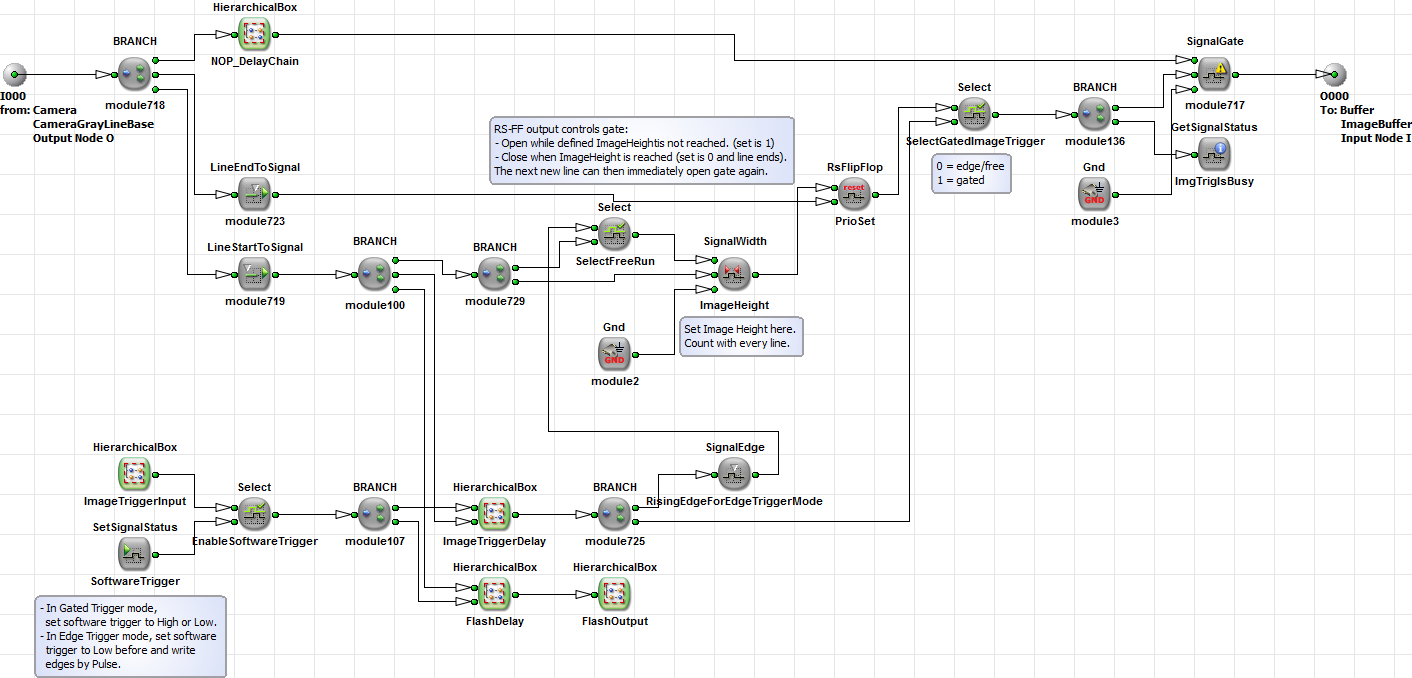
実装の他の部分は、入出力信号生成で構成されています。 これらの部分の実装はシンプルかつ直接的です。 フラッシュ出力信号は、h-box FlashOutput 内の TxSignalLine オペレーターを使用して Process1 に転送されます。 これは、フラッシュ信号を CC 信号にも出力する必要があるため求められます。
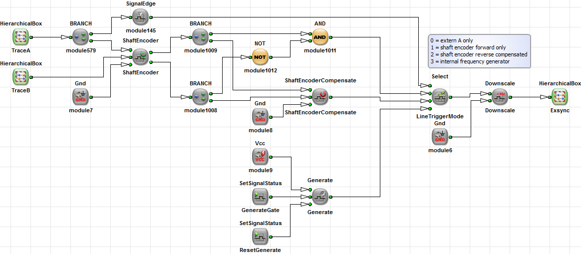
LineTrigger 階層ボックスは主に、入出力信号生成、ならびにシャフトエンコーダー解析および周波数ジェネレーターで構成されています。 シャフトエンコーダー信号解析用には、オペレーター ShaftEncoder および ShaftEncoderCompensate が使用されます。 LineTriggerMode Select スイッチにより、補正または 2 トランス解析を有効にするか無効にするかを個別に選択できます。 さらに、カメラをトリガーするために Generate オペレーターで表される内部周波数ジェネレーターが実装されています。
 前へ
前へ

