Operator Library: Signal
The operator analyzes two shaft encoder signal traces. The two traces are fed into the operator. At the outputs of the operator, a pulse for every encoder line as well as a direction signal are provided. The phase between the two trace signals are used for detection.
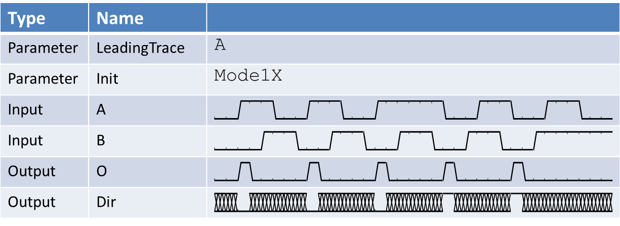
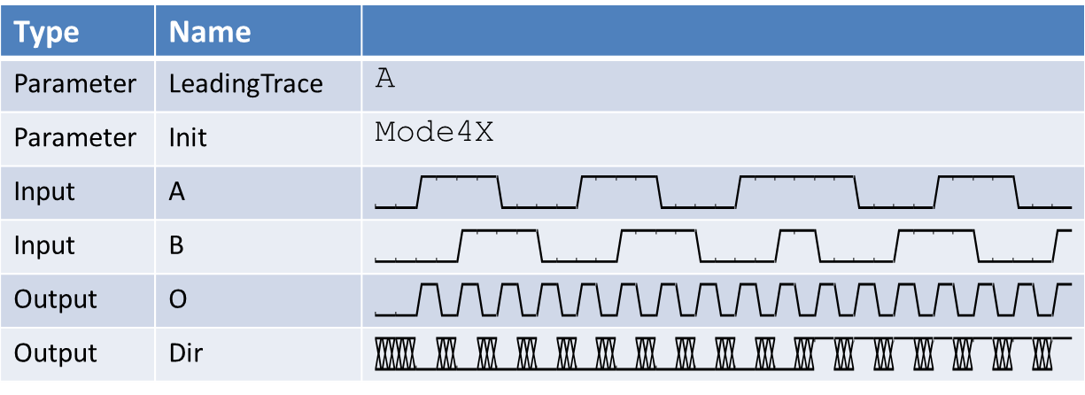
For every detected encoder line, the operator generates a pulse at its output link O. The pulse with is one design clock cycle. At output link Dir, the detected direction of the encoder is outputs. If Dir = 0 (LOW), a forward direction was detected. If Dir = 1 (HIGH), a reverse direction was detected. The values at the Dir output are only valid when output O is 1 (HIGH) i.e. a pulse is output.
Parameter LeadingTrace is used to define which one of the two traces is the leading trace, i.e. which trace is 90° ahead.
Parameter Mode defines the detection mode. The following modes can be used:
-
ModeX1:
Single Speed Mode. Only one edge of the leading signal is used for detection. The output is determined by:
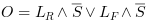

ここで、
 are the rising and falling edges of the leading trace e.g. A.
 is the slave trace e.g. B.
The following figure illustrates the behavior of the ModeX1
-
ModeX2:
Double Speed Mode. Both edges of the leading signal are used for detection. The output is determined by:

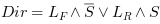
The following figure illustrates the behavior of the ModeX2
-
ModeX4:
Quad Speed Mode. All edges of the leading and the slave signal are used for detection. The output is determined by:

The following figure illustrates the behavior of the ModeX4
An additional reset input can be used to reset the operator to its initial state.
This operator is excluded from the VisualApplets functional simulation.
| Property | 値 |
|---|---|
| Operator Type | O |
| Input Links | TraceA, signal data input TraceB, signal data input Reset, signal data input |
| Output Links | O, signal data output of detected encoder lines Dir, signal data output of detected direction |
| Link Parameter | Input Link TraceA | Input Link TraceB | Input Link Reset | Output Link O | Output Link Dir |
|---|---|---|---|---|---|
| Bit Width | 1 | 1 | 1 | as TraceA | as TraceA |
| Arithmetic | unsigned | unsigned | unsigned | as TraceA | as TraceA |
| Parallelism | 1 | 1 | 1 | as TraceA | as TraceA |
| Kernel Columns | 1 | 1 | 1 | as TraceA | as TraceA |
| Kernel Rows | 1 | 1 | 1 | as TraceA | as TraceA |
| Img Protocol | VALT_SIGNAL | VALT_SIGNAL | VALT_SIGNAL | as TraceA | as TraceA |
| Color Format | VAF_GRAY | VAF_GRAY | VAF_GRAY | as TraceA | as TraceA |
| Color Flavor | FL_NONE | FL_NONE | FL_NONE | as TraceA | as TraceA |
| Max. Img Width | any | any | any | as TraceA | as TraceA |
| Max. Img Height | any | any | any | as TraceA | as TraceA |
| LeadingTrace | |
|---|---|
| タイプ | static/dynamic read/write parameter |
| Default | A |
| 範囲 | {A, B} |
|
This parameter specifies the leading trace. The leading trace is 90° ahead. |
|
| Mode | |
|---|---|
| タイプ | static/dynamic read/write parameter |
| Default | Mode1X |
| 範囲 | {Mode1X, Mode2X, Mode4X} |
|
This parameter defines the detection mode of the shaft encoder. See description above. |
|
The use of operator ShaftEncoder is shown in the following examples:
-
'Line Scan Trigger for microEnable 5 marathon VCL Using Signal Operators and Operator CameraControl'
A line scan trigger is presented. The trigger includes an image trigger using a capture gate as well as a multi functional line trigger. External sources, an internal frequency generator or software trigger pulses can be used for trigger generation.
-
'Line Scan Trigger for microEnable 5 marathon VCX QP Using Signal Operators'
A line scan trigger is presented. The trigger includes an image trigger using a capture gate as well as a multi functional line trigger. External sources, an internal frequency generator or software trigger pulses can be used for trigger generation.
-
'Line Scan Trigger for imaFlex CXP-12 Quad Using Signal Operators'
A line scan trigger for CoaXPress12 is presented. The trigger includes an image trigger using a capture gate as well as a multi functional line trigger. External sources, an internal frequency generator or software trigger pulses can be used for trigger generation.
