Operator Library: Filter
The operator FIRkernelNxM creates rectangular kernel window around each pixel, which includes the neighbor pixels. The size of the kernel can be defined by editing the output link. N represents the number of kernel rows and M the number of kernel columns.
![[Note]](../common/images/admon/note.png) |
No FIR filter |
|---|---|
|
In contrast to its name, the operator has nothing to do with a FIR filter. It can be used to produce the filter input data. |
Other operators to generate kernels are the operators LineNeighboursNx1 and PixelNeighbours1xM.
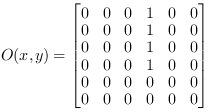
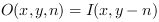
The central element of a kernel always represents the original input pixel of the respective position. The output image O with pixel indices x and y and kernel indices m and n is derived from the input by:
with
 and
and
At image edges, no neighbored pixels are defined. The operator allows the definition of the required edge handling algorithm using the parameter EdgeHandling.
For kernels of even size, there is no central pixel. In this case, the central pixel is displaced to the upper left corner, e.g. for a kernel of size 4x4 defines the central pixel at (1,1) as can be seen in the following table.
| 0,0 | 0,1 | 0,2 | 0,3 |
| 1,0 | 1,1 | 1,2 | 1,3 |
| 2,0 | 2,1 | 2,2 | 2,3 |
| 3,0 | 3,1 | 3,2 | 3,3 |
Kernels are described by the number of rows and columns. In VisualApplets, N represents the number of rows, and M represents the number of columns. Often, kernel elements are addressed by their index instead of their coordinate. In this case, the order is row by row as shown in the following table.
| 0 | 1 | 2 | 3 |
| 4 | 5 | 6 | 7 |
| 8 | 9 | 10 | 11 |
| 12 | 13 | 14 | 15 |
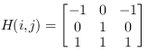
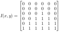
The following example shows the resulting composition for three kernel rows and three kernel columns. The 3x3 matrix in the depicted operator provides the relative addressing that defines the content of the respective kernels. Each 3x3 cluster on the output shows the different kernel values per pixel.

Instead of kernel configurations per pixel, this example shows the resulting subkernels: the first kernel at index 0 and the last kernel at index 8.

The following example shows the resulting composition for two kernel rows and two kernel columns. As the relative addresses only reference neighbors on the right hand side or below, no edge handling needs to be performed for content to the left or at top.

Comparing the last two examples with odd and even kernel sizes shows a noticeable behavior of the edgeHandling feature in edgeMirroring mode. While edgeMirroring for even and odd kernel sizes is treated identically on top and left borders, it produces slightly different results on the bottom and the right hand side. Due to the large output image size only the resulting configurations for the first, upper right, and last, lower right, input pixel with their resulting values per kernel are presented:

EdgeMirroring for odd kernel sizes fills regions with missing data from equidistant regions with data. The border is preserved and not replicated. The same principle is valid for filling regions to the top or to the left for even kernel sizes. In contrast to this, filling regions to the bottom or to the right replicates the border during mirroring. Again, this only occurs for even kernel sizes.
![[Tip]](../common/images/admon/tip.png) |
EdgeMirroring for even kernel sizes |
|---|---|
|
For even kernel sizes, filling regions to the bottom or to the right replicates the border during mirroring. |
Technically, the operator waits and buffers the required pixels of the kernel until they can be output in parallel. Therefore, the operator will cause a delay as pixels can only be output after all required respective neighbor pixels were processed at the input. The line delay is:
Operator Restrictions
-
ImageWidth < 2*Parallelism is not allowed.
-
Empty images, i.e. images with no pixels, are not allowed.
-
Empty lines or varying line lengths are not allowed.


|
|
The range of the input bit width is:
|
|
|
If VALT_LINE1D image protocol is used, the operator is of type P instead of type M. |
|
|
OutputKernelColumns <= ImageWidth |
|
|
OutputKernelRows <= ImageHeight |
| EdgeHandling | |
|---|---|
| タイプ | static parameter |
| Default | EdgeMirrored |
| 範囲 | {EdgeMirrored, EdgeConstant} |
|
At image edges, no neighbors exist to generate a kernel. In this case, the operator can be used in two edge handling modes: In mode EdgeMirrored, mirrored pixels are used at the image edges. In mode EdgeConstant, the missing kernel elements at the edges are filled by a constant value. This value can be defined using the parameter Constant. |
|
| Constant | |
|---|---|
| タイプ | static parameter |
| Default | 0 |
| 範囲 | range of input link I |
|
If the parameter EdgeHandling is set to EdgeConstant, this parameter defines the default value for a pixel outside the image borders. For color formats, the value is an unsigned integer combining the binary representations of all color components. |
|
The use of operator FIRkernelNxM is shown in the following examples:
-
Synchronization - Avoiding deadlocks.
-
A binarization example for local adaptive thresholding. A kernel size of 8 by 8 pixel is used.
-
'Nearest Neighbor Demosaicing'
Examples - Nearest Neighbor Bayer Demosaicing
-
Examples - The example shows the demosaicing of a Bayer RAW pattern using a 3x3 filter.
-
Examples - The example shows the demosaicing of a Bayer RAW pattern using a 5x5 filter.
-
'Bayer 3x3 Demosacing with White Balancing'
Examples - The example shows the demosaicing of a Bayer RAW pattern using a 3x3 filter. Moreover, a white balancing for color correction is added.
-
'Bayer 5x5 Demosacing with White Balancing'
Examples - The example shows the demosaicing of a Bayer RAW pattern using a 5x5 filter. Moreover, a white balancing for color correction is added.
-
'Edge Sensitive Bayer Demosaicing Algorithm'
Examples - Edge Sensitive Laplace Bayer Demosaicing filter
-
'Bayer Demosaicing Algorithm According to Laroche'
Examples - Laroche Bayer Demosaicing filter
-
'Modified Laroche Bayer Demosaicing Algorithm '
Examples - Ressource Optimized Laroche Bayer Demosaicing filter
-
Examples - The example shows the demosaicing of a Bayer RAW pattern of a bilinear line scan camera with color pattern Red/BlueFollowedByGreen_GreenFollowedByBlue/Red
-
Examples - The example shows the demosaicing of a Bayer RAW pattern of a bilinear line scan camera with color pattern Red/BlueFollowedByBlue/Red_GreenFollowedByGreen
-
'Bayer Demosaicing a Line Scan Camera with 8 Bit BiColor Bayer Pattern'
Examples - This example shows the demosaicing of a Bayer 8 bit RAW pattern of a CXP-12 line scan camera with BiColor Bayer pattern: BiColorRGBG, BiColorGRGB, BiColorBGRG and BiColorGBGR, for example for the racer 2 L camera. In addition, the example contains a line scan trigger module and a white balancing module.
-
'Bayer Demosaicing a Line Scan Camera with 10 Bit BiColor Bayer Pattern'
Examples - This example shows the demosaicing of a 10 bit Bayer RAW pattern of a CXP-12 line scan camera with BiColor Bayer pattern: BiColorRGBG, BiColorGRGB, BiColorBGRG and BiColorGBGR, for example for the racer 2 L camera. In addition, the example contains a line scan trigger module and a white balancing module.
-
'Bayer Demosaicing a Line Scan Camera with 12 Bit BiColor Bayer Pattern'
Examples - This example shows the demosaicing of a 10 bit Bayer RAW pattern of a CXP-12 line scan camera with BiColor Bayer pattern: BiColorRGBG, BiColorGRGB, BiColorBGRG and BiColorGBGR, for example for the racer 2 L camera. In addition, the example contains a line scan trigger module and a white balancing module.
-
Examples - The coprocessor feature of the imaFlex platform is shown. As an example, a median filter is calculated.
-
'Co-Processor Large Filter Calculation'
Examples - The coprocessor feature of the imaFlex platform is shown. As an example, a large filter kernel is calculated.
-
Examples - A binary eroded image is compared with the original. An edge is detected if both differ.
-
Examples - The Kirsch filter is a good edge detection filter for non directional edges.
-
Examples - A Sobel filter in x-direction only.
-
Examples - A Sobel filter in all 4 directions.
-
Examples - Shows the implementation of a morphological close applied to binary images.
-
Examples - Shows the implementation of a morphological open applied to binary images.
-
Examples - A simple 3x3 box filter.
-
Examples - A Gauss filter using a 5x5 kernel.
-
Examples - Applet applies a 5x5 median filter on the image.
-
Examples - Explains the implementation of filters.
-
Examples - An example of the use of two filters in parallel.
-
Examples - Shows how to extract a sub kernel from a filter to obtain the original image data. This example performs a simple local adaptive binarization.
-
'Filter for Line Scan Cameras'
Examples - Explains how to implement a filter for line scan cameras.
-
'High Boost Sharpening Filter'
Examples - A high boost Laplace filter for sharpening
-
Examples - A 3x3 Laplace filter.
-
Examples - A convolution with high intensity spot coefficients is made. For results above threshold, the respective pixels are dyed in red.
-
'Depth From Focus Using Loops'
Examples - Depth From Focus using Loops
-
'Normalized Cross Correlation'
Examples-
-
Examples - The examples shows an automatic dead pixel detection and replacement.
