With VisualApplets, you have the possibility to convert image processing modules you have designed in VHDL into VisualApplets operators.
You incorporate your modules as IP cores into VisualApplets. Each IP core builds one operator. After implementation, these operators work like built-in VisualApplets operators. Operators implemented in such a way are called custom operators.
To make your custom operators available on the VisualApplets GUI, you also need to define one or more custom libraries that contain the custom operator(s.) Each custom operator needs to be part of one specific custom library.
You add a new custom operator to VisualApplets in just a few steps. You can complete the whole work flow by your own:
-
Specify the custom operator’s main properties and its interface directly on the VA GUI (operator name, operator version, number and properties of required image in, image out, memory ports, etc.).
-
Based on your input of step 1, let VisualApplets generate the VHDL code for the operator interface (black box) and a VHDL test bench for testing your implementation.
-
Wrap your HDL code so that its interface matches the generated black box. For testing your implementation the automatically generated test bench may help.
-
Create a net list of your implementation. Also create a constraints file if required.
-
Optionally, create the operator documentation (for the operator help window) and a simulation model (that later allows to simulate a VA design containing the custom operator).
-
Edit the custom operator in VA again: Add the generated netlist and optionally also the help files and simulation model.
After these steps, your image processing module is available as custom operator directly
in VisualApplets and can be used the same way as any other operator. The custom libraries are
saved as *.val or *.vl files (similar to the user libraries). They can be deployed
and distributed in this format.
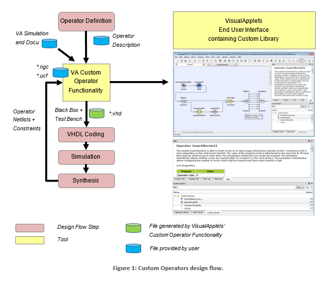
VisualApplets (i.e., the VisualApplets Custom Operator Functionality) is used two times during this work flow:
-
For the generation of an operator prototype in VisualApplets allowing to export HDL code for defining the concerning IP core interface (black box and test bench).
-
For completing the operator by adding the necessary files for synthesis and (optionally) simulation and help content.
Generation of Operator Prototype: The VA Custom Operator Functionality lets you create an operator prototype which can immediately be used for instantiating the operator in Visual Applets. For this operator prototype a black box interface and an RTL level simulation entity for emulating the communication ports of the generated operator interface can be exported. Then you can start coding (i.e., implementing your HDL code complying with the interface of the black box) and simulating your custom operator design. The resulting FPGA design you then synthesize to an EDIF or NGC netlist. Optionally, you add a constraints file, create a dynamic link library for VisualApplets high-level simulation, and write HTML documentation for the VisualApplets GUI.
Completing the operator definition: The VA Custom Operator Functionality lets you specify the netlist, simulation library and documentation files. Supplemented with these files the operator is ready for use immediately.
VisualApplets knows different types of operators and ports, depending on the underlying flow control mechanism. Operators may be of type O or type M.
![[Tip]](../common/images/admon/tip.png) |
Custom Operator Type: M |
|---|---|
|
Custom operators are always of type M. |
Operator ports can be synchronous or asynchronous. Being synchronous in VisualApplets basically means that data of several ports is transferred synchronously, whereas ports which are asynchronous to each other support non-aligned communication patterns.
Ports are only synchronous if they have a common M-source, or if they are sourced from a SYNC module; any constellation of O-operators may be between that source and the ports.
Depending on the relation of the operator input ports to each other, we differentiate between the following options:
-
Synchronous inputs: All input ports are synchronous to each other. There is one output port.
-
Asynchronous inputs: Some of the input ports are asynchronous to each other and all outputs are synchronous to each other.
Operators with asynchronous outputs are not allowed. Operators with synchronous inputs may only have a single output. If more than one output is required, the inputs must be declared as being asynchronous.
|
Defining Multiple Outputs |
|---|---|
|
If you want to create an operator with multiple outputs, you need to declare its inputs to be asynchronous. Multiple outputs are always synchronous. |
Examples for both classes (built-in Visual-Applets operators):
|

|
RemoveImage |
M-Operator with synchronous inputs and one output. |
|

|
SYNC |
M-Operator with asynchronous inputs and multiple, synchronous outputs. |
VisualApplets custom operator interfaces are designed for smoothly integrating your new operators so they behave inside VisualApplets like built-in operators. You can define any number of input and output ports for your custom operators.
-
Image In / Image Out: The Image In and Image Out ports may support multiple image formats. They are driven by simple-to-use FIFO interfaces. The FIFOs reside in the VA part of the custom operator, so that you only need to implement a flow control, but not the FIFO.
-
Memory ports: You also can define any number of memory ports. They also use FIFOs residing in the VA part of the custom operator.
-
GPIO ports: In addition to the image ports, you can define general-purpose I/O ports, e.g., for communicating asynchronous signals to the operator.
-
Registers: To allow the final user of your operator to configure the operator and to get access to status information, you can define any number of write and read registers.
-
Clock: The ports for receiving clock pulses are set up automatically for every custom operator.
-
Reset/Enable port: The ports for receiving reset or enable commands are set up automatically for every custom operator.
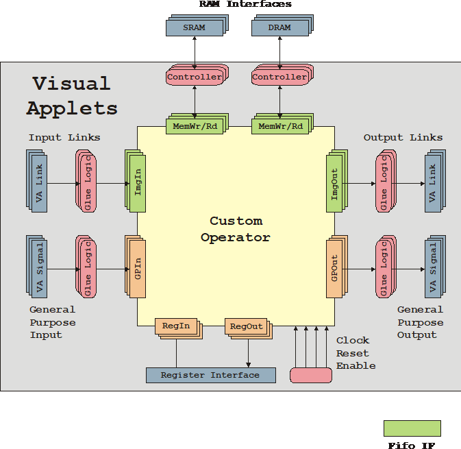
The following sections describe the different types of interfaces shown in the above figure in detail.
VisualApplets connects two clock inputs – the design clock and a second clock synchronous to the design clock but with double frequency. All interfaces except the memory interface must be synchronous to the design clock. The memory interface may be configured using the design clock or the double frequency clock for the read and/or write interface.
The Reset and Enable inputs are driven by the according “process enable” and “process reset” signals of the VA-process where the operator is instantiated. Make sure you implement the following behavior as reaction to these signals into your operator:
-
Assertion of Reset puts the operator in its init state.
-
Assertion of Enable starts processing.
-
Deactivating Enable stops processing.
-
(When Enable=0, the output FIFOs of the operator are not read. Depending on the state of the image processing pipeline some data may still be written to the input ports but the flow control safely prevents that any FIFO content gets corrupted.)
-
Reset is only asserted when Enable=0
The following behavior to these signals is implemented in the VA part of the custom operator:
-
Reset will empty all port interface FIFOs.
-
Reset and Enable have no effect on the parameters of the operator.
-
Reset and Enable have no effect on the GPIO interface of the operator.
For communicating operator parameters and status, the custom operator may be supplied with an arbitrary number of VisualApplets parameters. Each of the parameters translates to a separate register port of the custom operator. VisualApplets cares for dispatching the accesses to and from the operator registers.
You can define the image protocols that will be supported by the image in and image out ports of your custom operator. The future user of your operator will then be able to select from the list of image protocols you provide.
VisualApplets offers the following image formats to be supported by your operator’s ImgIn and ImgOut ports:
-
grayXxP: gray image with X bits per pixel and parallelism P
-
rgbYxP: color image with Y/3 bits per color component (red, green, blue) and parallelism P
-
hsiYxP: color image with Y/3 bits per color component (HSI color model) and parallelism P
-
hslYxP: color image with Y/3 bits per color component (HSL color model) and parallelism P
-
hsvYxP: color image with Y/3 bits per color component (HSV color model) and parallelism P
-
yuvYxP: color image with Y/3 bits per color component (YUV color model) and parallelism P
-
ycrcbYxP: color image with Y/3 bits per color component (YCrCb color model) and parallelism P
-
labYxP: color image with Y/3 bits per color component (LAB color model) and parallelism P
-
xyzYxP: color image with Y/3 bits per color component (XYZ color model) and parallelism P
Additionally, the image dimension and the information whether pixel components are signed or unsigned can be coded by optional suffixes.
The pixel data width X is limited to 64 bit. The width Y must be a multiple of 3 and is limited to 63 bit. The parallelism P defines the number of pixels which are contained in a single data word at the interface port. It must be chosen from following set of allowed values: P = {1, 2, 4, 8, 16, 32, 64}.
Packing of image data into words of a given interface width N must follow certain rules:
-
The data of all P pixels must fit in a single word of length N. The data is stored LSB aligned which means that for a pixel width Z (Z=X for grey, Z=Y for color) data is distributed as follows: Pixel[0]->Bits[0..Z-1] .. Pixel[P-1]->Bits[(P-1)*Z..P*Z-1].
-
For RGB images the three color components are packed LSB aligned into a sub word [0..Y-1] in the following order: red uses the bits [0..Y/3-1 ], green the bits [Y/3..2*Y/3-1] and blue the bits [2*Y/3..3*Y/3-1].
-
For YUV color images the same rules than for RGB applies where Y takes the role of red, U that of green and V the role of blue.
-
For HSI color images the same rules than for RGB applies where H takes the role of red, S that of green and I the role of blue.
-
For LAB color images the same rules than for RGB applies where L takes the role of red, A that of green and B the role of blue.
-
For XYZ color images the same rules than for RGB applies where X takes the role of red, Y that of green and Z the role of blue.
In VisualApplets, any link carries the properties maximum image width and maximum image height. VisualApplets lets you define optional constraints for the maximum width and height for any of the supported image protocols of the custom operator separately.
For an image interface port, you define a list of allowed image protocols. This list makes up a subset of the possible VisualApplets image formats (see above). A format can be described by the following properties:
-
Data type uint or int
-
Pixel data bit width N = [1..64]
-
Gray or color format (single or three data components with aggregated width N)
-
Flavor of color format (RGB, HSI, HSL, HSV, YUV, YCrCb, LAB, XYZ)
-
2D, 1D, or 0D
-
Parallelism P = {1,2,4,8,16,32,64}
Implicitly it is assumed that the kernel size is 1x1. The listed formats are numbered starting from zero and therewith define an ID.
When working with the final operator in VisualApplets, the user of your operator can select any of the formats you list here for the image communication port in question. According to the selection made by the VA user, the corresponding ID will be output to the related custom operator port.
This enables the custom operator to adapt its behavior to the selected format.
Image input ports allow to communicate image data from the VisualApplets process to the custom operator. These ports are named ImgIn. If you designed the custom operator to support configuration of its input channel(s) (see section 'Image Protocols'), several different protocols can be driven through a single port selected by the corresponding format parameter within VisualApplets. The interface basically consists of a FIFO and a parameter register providing an ID for the actually used data format. The custom operator must care for reading the FIFO and interpreting the image data according to the protocol of the selected image format. The operator must guarantee a correct flow control according to the status pins providing information about the filling state of the FIFO, i.e., no data may be read when the FIFO is empty.
For an image interface port, a list of allowed image formats needs to be defined. This list makes up a subset of possible VisualApplets image formats (see section 'Image Protocols') where a format can be described by the following properties:
-
Data type uint or int
-
Pixel data bit width N = [1..64]
-
Gray or color format (single or three data components with aggregated width N)
-
Flavor of color format (RGB, HSI, HSL, HSV, YUV, YCrCb, LAB, XYZ)
-
2D, 1D, or 0D
-
Parallelism P = {1,2,4,8,16,32,64}
Implicitly it is assumed that the kernel size is 1x1. The listed formats are numbered starting from zero and therewith define an ID.
When working with the final operator in VisualApplets, the user can select any of the formats you list here for the concerning image communication port. According to the selection made by the VA user, the corresponding ID will be output to the related Custom Operator port. This enables the custom operator to adapt its behavior to the selected format.
Image output ports allow communicating image data from the custom operator to the VisualApplets process. These ports are named ImgOut. If you designed the custom operator to support appropriate configuration of its output channel(s) (see section 'Image Protocols'), several different protocols can be driven through a single port selected by the corresponding format parameter within VisualApplets. The interface basically consists of a FIFO and a parameter register providing an ID for the actually used data format. The custom operator must care for feeding the FIFO with image data according to the protocol of the selected image format. The operator must guarantee a correct flow control according to the status pins providing information about the filling state of the FIFO, i.e., no data may be written when the FIFO is full.
For an image interface port, a list of allowed image formats needs to be defined. This list makes up a subset of possible VisualApplets image formats (see section 'Image Protocols') where a format can be described by the following properties:
-
Data type uint or int
-
Pixel data bit width N = [1..64]
-
Gray or color format (single or three data components with aggregated width N)
-
Flavor of color format (RGB, HSI, HSL, HSV, YUV, YCrCb, LAB, XYZ)
-
2D, 1D, or 0D
-
Parallelism P = {1,2,4,8,16,32,64}
Implicitly it is assumed that the kernel size is 1x1. The listed formats are numbered starting from zero and therewith define an ID.
When working with the final operator in VisualApplets, the user can select any of the formats you list here for the concerning image communication port. According to the selection made by the VA user, the corresponding ID will be output to the related custom operator port. This enables the custom operator to adapt its behavior to the selected format.
The General Purpose I/O interface allows connecting dedicated signal pins of the custom operator. Every GPIO port maps to a pin of the custom operator which is either an input or an output.
Bidirectional pins are not supported. In VisualApplets, the corresponding operator ports are of type SIGNAL.
|
Bidirectional Pins not Supported |
|---|---|
|
The GPIO pins must be either an input or an output. Bidirectional pins are not supported. |
A custom operator may be set up for accessing one or more banks of memory. The concerning memory ports have a FIFO like interface for write and read commands. The FIFOs reside in the VA part of the custom operator, so that you only need to implement a flow control, but not the FIFO. The timing of forwarding the FIFO content to the memory controller attached to the custom operator is fully controlled by VisualApplets.
First of all, you need to enter some details describing your new custom operator.
VisualApplets uses these details for generating a VHDL black box for your custom operator and an according test bench for simulation.
You enter the configuration for your individual custom operator via the VisualApplets GUI. VisualApplets makes the specified operator available for use in a design immediately, even if the operator specification is incomplete concerning netlist, simulation model and documentation.
|
Custom Library File |
|---|---|
|
A custom library with all contained operators is stored as one single This file can be distributed and directly applied in VisualApplets. It simply needs to be copied into the Custom Library directory which is specified in the VisualApplets settings. |
|
Operator Configuration in XML Format |
|---|---|
|
VisualApplets stores the custom operator specification in XML format. You can export the XML content from the custom library to a file, e.g., for handling it in a version control system. On the other hand you can import the XML for adding a custom operator (see section 'Importing and Exporting Individual Custom Operators'). You do not need to know how this XML file looks like. However, if you want to have a look, refer to section 'XML Format for Custom Operator Specification'. |
Before you can start to define a new custom operator, you need to create a custom library where the new operator belongs to.
If you already have a custom library available where the new custom operator will belong to, skip this section and proceed with section 'Creating a New Custom Operator'.
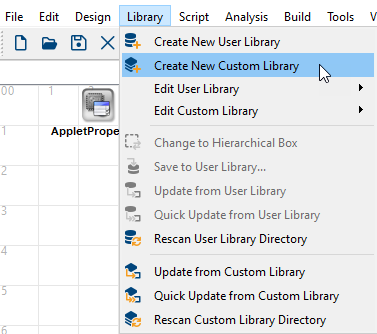
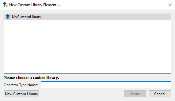
To create a new custom library:
-
In menu , select menu item .
-
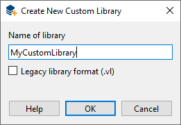
Give a name to your new custom library.
-
By default, the new custom operator library is saved in the
*.valfile format. If you want to open this library in VisualApplet version 3.3.2 or older, select . -
Click
|
Comply with Conventions for Valid C Identifiers |
|---|---|
|
When defining the library name, make sure you adhere to the conventions for valid C identifiers. |
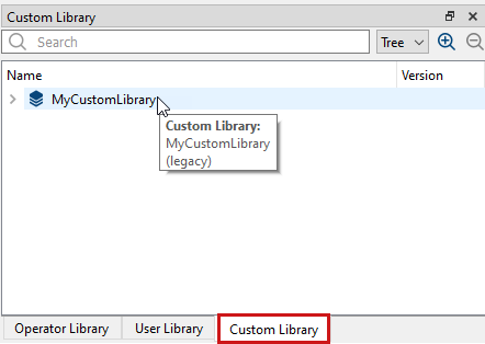
Now, the new custom library is created. You can see it in the operator panel under the tab:
When you move the mouse over the custom library name, a tooltip shows whether the library is saved in the *.vl legacy file format:
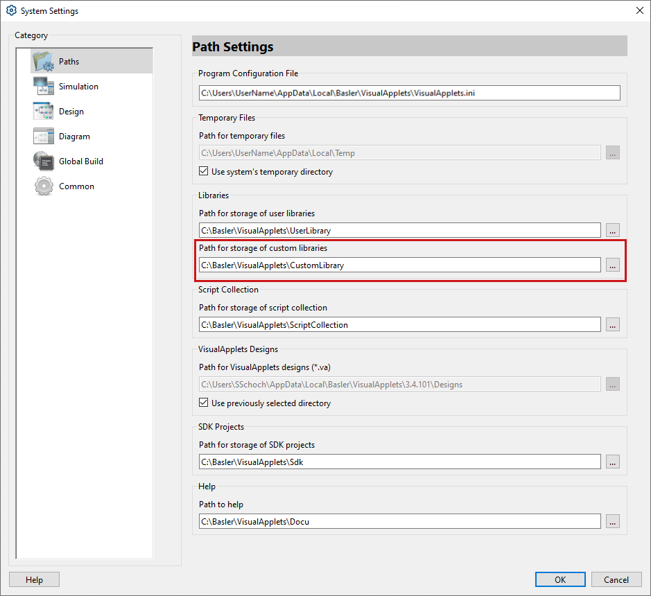
For creating a new custom library, you may need to specify a directory where all custom-library-related files are stored. You do this under → → .
To define a new custom operator:
-
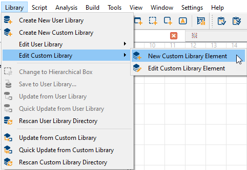
In menu , select menu item .
-
In the submenu that opens, select .
-
In the window that opens, select a custom library via double-click on the library name.
-
Enter a name for your custom operator:
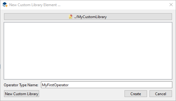
Comply with VHDL Naming Conventions When defining the operator name in the VA GUI, make sure you conform to the VHDL naming conventions.
VHDL valid names are defined as follows:
“A valid name for a port, signal, variable, entity name, architecture body, or similar object consists of a letter followed by any number of letters or numbers, without space. A valid name is also called a named identifier. VHDL is not case sensitive. However, an underscore may be used within a name, but may not begin or end the name. Two consecutive underscores are not permitted.“
-
Before saving, you must define the properties of your new operator:
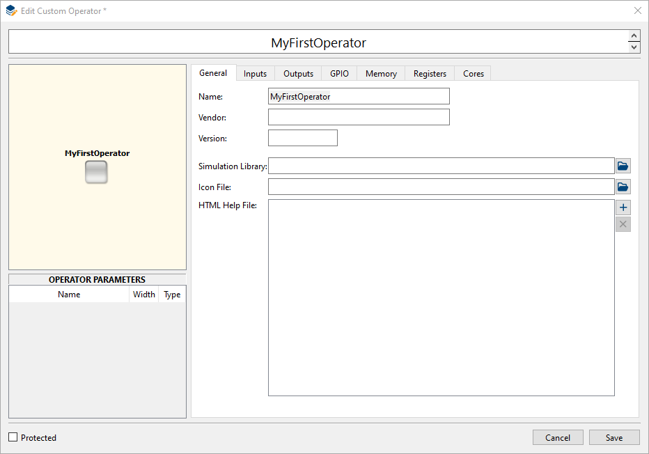
For detailed information about defining the properties of your new custom operator, see 'Defining Basic Information about Custom Operator'.
-
Click the button.
The dialog opens. Here, you can define your custom operator.
-
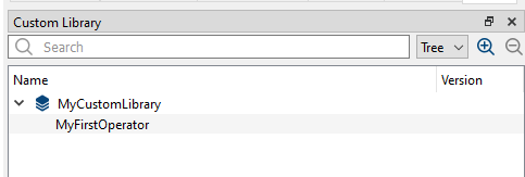
Click the button.
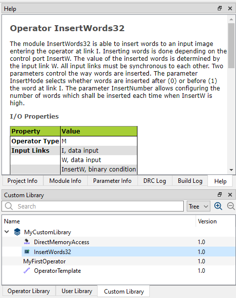
Now, your new custom operator is visible under the custom library it belongs to:
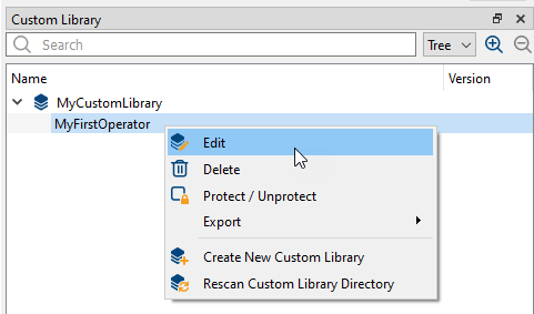
Once you have created a new custom operator and saved it to VisualApplets, you can interrupt your work and proceed any time. To proceed, you go to the Custom Library tab, open the library, right-click on the operator name, and from the sub menu, select Edit.
|
Use Operator Template Instead |
|---|---|
|
Alternatively, you can use the custom operator template provided in your VisualApplets installation to define new custom operators. How to use the template, see section 'Custom Operator Template'. |
In a first step, you define your custom operator’s interface.
-
Provide your vendor name. You can enter any string. This information is intended for operator identification by the user.
-
Provide a version number for your operator, e.g., version 1.0. You can enter any number but you should comply with the version scheme <major>.<minor>. This information is intended for operator version identification by the user.

-
Proceed to the tab .
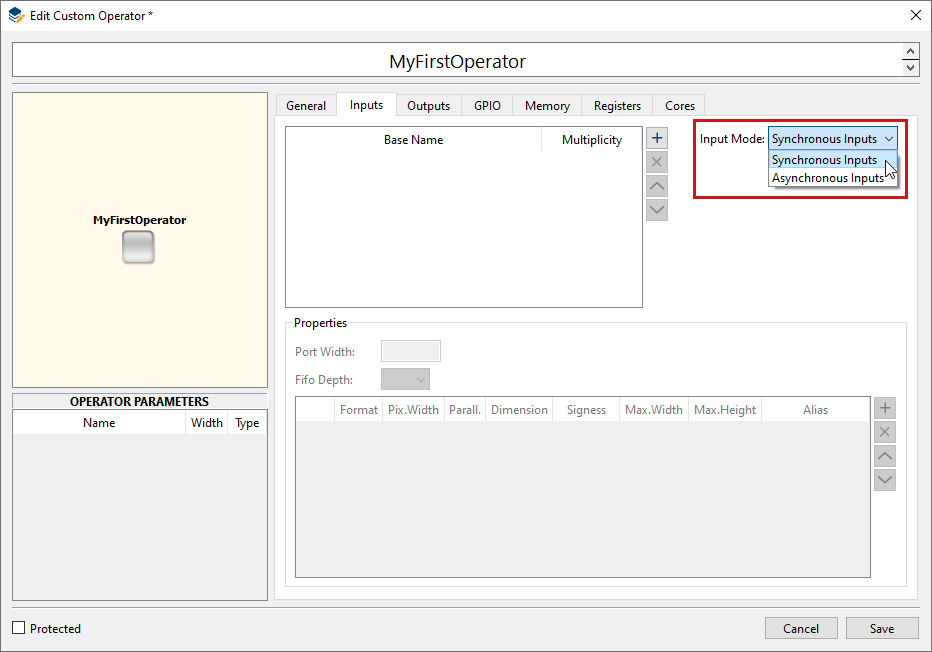
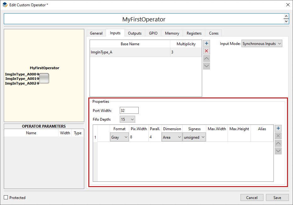
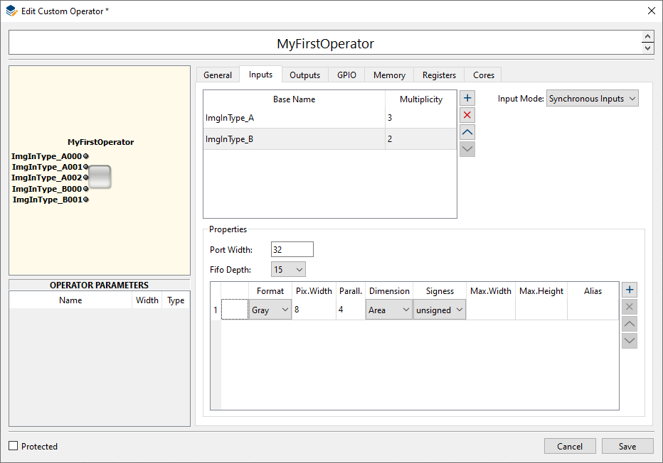
Under tab , you describe the properties of the image input ports.
-
First of all, you define the input mode of your custom operator’s ImgIn ports:
|
Synchronous and Asynchronous Operator Ports | |||||
|---|---|---|---|---|---|---|
|
Operator ports can be synchronous or asynchronous. Being synchronous in VisualApplets basically means that data of several ports is transferred synchronously, whereas ports which are asynchronous to each other support non-aligned communication patterns. Ports are only synchronous if they have a common M-source, or if they are sourced from a SYNC module; any constellation of O-operators may be between that source and the ports. Depending on the relation of the operator input ports to each other, we differentiate between the following options:
Operators with asynchronous outputs are not allowed. Operators with synchronous inputs may only have a single output. If more than one output is required, the inputs must be declared as being asynchronous. If you want to create an operator with multiple outputs, you need to declare its inputs to be asynchronous. Multiple outputs are always synchronous. Examples for both classes (built-in VisualApplets operators):
|


You can define one or more image input ports (ImgIn). Each ImgIn port may be used as often as you specify.
-
Click on the ボタン
 to create a first image in (ImgIn) port.
-
Give a name to the ImgIn port and define the number of input ports in the field: >1 defines an array of ports with a name consisting of the base name and an index.
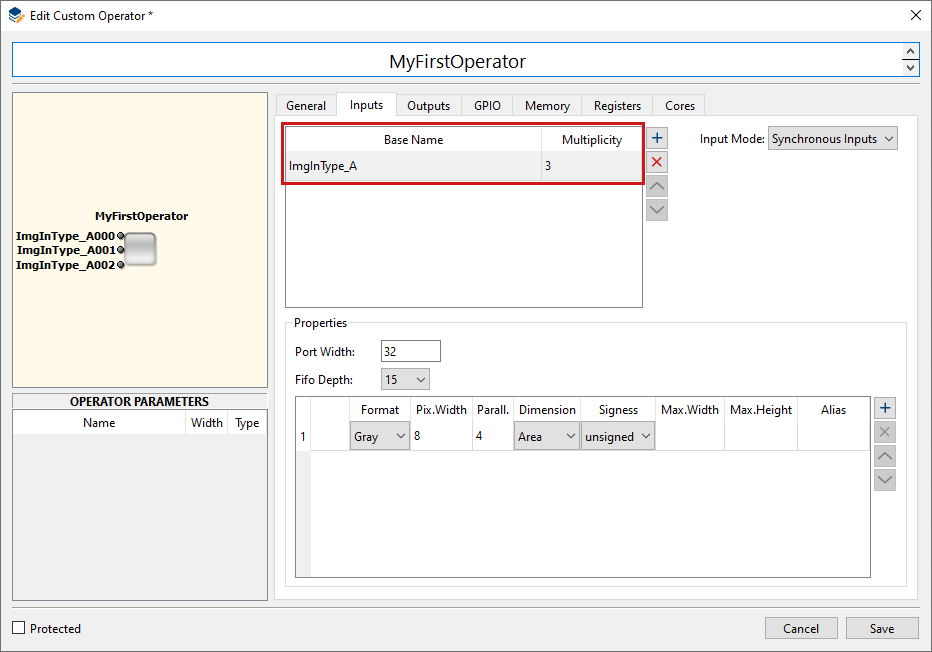
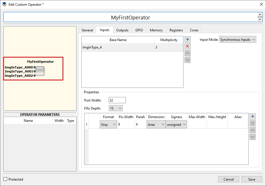
Immediately, the operator depiction in the program window displays the entered array of ImgIn ports:
-
In the panel, you specify the properties of the protocols that are supported by this ImgIn port.
-
Under , specify the width of the ImgIn port.
-
Under , specify the depth of the buffer FIFO for input data which at least needs to be provided by the VA core. The value must be a power of two minus 1 between 15 and 1023.
For an image interface port, you define a list of allowed protocols. A protocol can be described by the following properties:
-
Gray or color format (single or three data components with aggregated width N)
-
Flavor of color format (RGB, HSI, HSL, HSV, YUV, YCrCb, LAB, XYZ)
-
Pixel data bit width N = [1..64]
-
Parallelism P = {1,2,4,8,16,32,64}
-
2D (Aray), 1D (Line), or 0D (Raw)
-
Data type uint or int
-
Max. image dimensions
Implicitly it is assumed that the kernel size is 1x1.
The listed protocols are numbered starting from zero and therewith define an ID (in the image below visible in the left hand column of the table in the panel).
If you specify more than one protocol, you design the custom operator to support configuration of its input channel(s). In this case, several different protocols can be driven through a single port.
The user of your custom operator can select the protocol he wants to use on a specific ImgIn port. According to the selection made by the VA user, the corresponding ID will be output to the related custom operator port. This enables the custom operator to adapt its behavior to the selected protocol.
-
-
Under , specify the color format of the protocol.
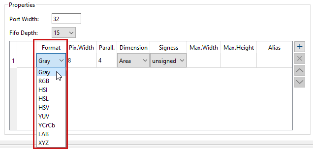
The following color formats are allowed:
-
grayXxP: gray image with X bits per pixel and parallelism P
-
rgbYxP: color image with Y/3 bits per color component (red, green, blue) and parallelism P
-
hsiYxP: color image with Y/3 bits per color component (HSI color model) and parallelism P
-
hslYxP: color image with Y/3 bits per color component (HSL color model) and parallelism P
-
hsvYxP: color image with Y/3 bits per color component (HSV color model) and parallelism P
-
yuvYxP: color image with Y/3 bits per color component (YUV color model) and parallelism P
-
ycrcbYxP: color image with Y/3 bits per color component (YCrCb color model) and parallelism P
-
labYxP: color image with Y/3 bits per color component (LAB color model) and parallelism P
-
xyzYxP: color image with Y/3 bits per color component (XYZ color model) and parallelism P
-
-
Double-click in the field of column and specify the pixel data width for the specific format:
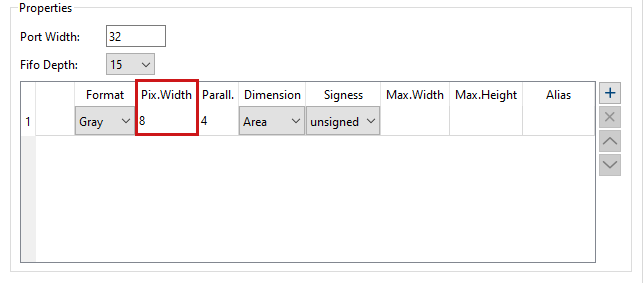
The value range of Pix.Width depends on your choice under :
Gray: The pixel data width (in the following referred to as X) is limited to 64 bit.
All color formats: The pixel data width (in the following referred to as Y) must be a multiple of 3 and is limited to 63 bit.
-
Double-click in the field of column and specify the parallelism for the specific format.
The parallelism defines the number of pixels which are contained in a single data word at the interface port. It must be chosen from following set of allowed values: P = {1, 2, 4, 8, 16, 32, 64}. Packing of image data into words of a given interface width N (specified under ) must follow certain rules:
-
The data of all P pixels must fit in a single word of length N. The data is stored LSB aligned which means that for a pixel width Z (Z=X for grey, Z=Y for color) data is distributed as follows: Pixel[0]->Bits[0..Z-1] .. Pixel[P-1]->Bits[(P-1)*Z..P*Z-1].
-
For RGB images the three color components are packed LSB aligned into a sub word [0..Y-1] in the following order: red uses the bits [0..Y/3-1 ], green the bits [Y/3..2*Y/3-1] and blue the bits [2*Y/3..3*Y/3-1].
-
For HSI color images the same rules than for RGB applies where H takes the role of red, S that of green and I the role of blue.
-
For HSL color images the same rules than for RGB applies where H takes the role of red, S that of green and L the role of blue.
-
For HSV color images the same rules than for RGB applies where H takes the role of red, S that of green and V the role of blue.
-
For YUV color images the same rules than for RGB applies where Y takes the role of red, U that of green and V the role of blue.
-
For YCrCb color images the same rules than for RGB applies where Y takes the role of red, Cr that of green and Cb the role of blue.
-
For LAB color images the same rules than for RGB applies where L takes the role of red, A that of green and B the role of blue.
-
For XYZ color images the same rules than for RGB applies where X takes the role of red, Y that of green and Z the role of blue.
-
-
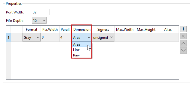
Under , specify if the protocol supports 2D (Area), 1D (Line), or 0D (Raw) images.
-
: Using these optional fields you can define constraints for the image width and image height.
-
Repeat steps 6 to 10 to define as many protocols as you want the ImgIn port to support.
-
Repeat steps 1 to 11 to define as many ImgIn ports you want your custom operator to provide.
Under tab , you describe the properties of the image output ports.
You can define one or more image output ports (ImgOut). Each ImgOut port may be used as often as you specify.
-
Click on the ボタン
to create a first image out (ImgOut) port.
-
Give a name to the ImgOut port.
-
Double-click in the field of the column to create an array of ports. Multiplicity >1 defines an array of ports with a name consisting of the base name and an index.
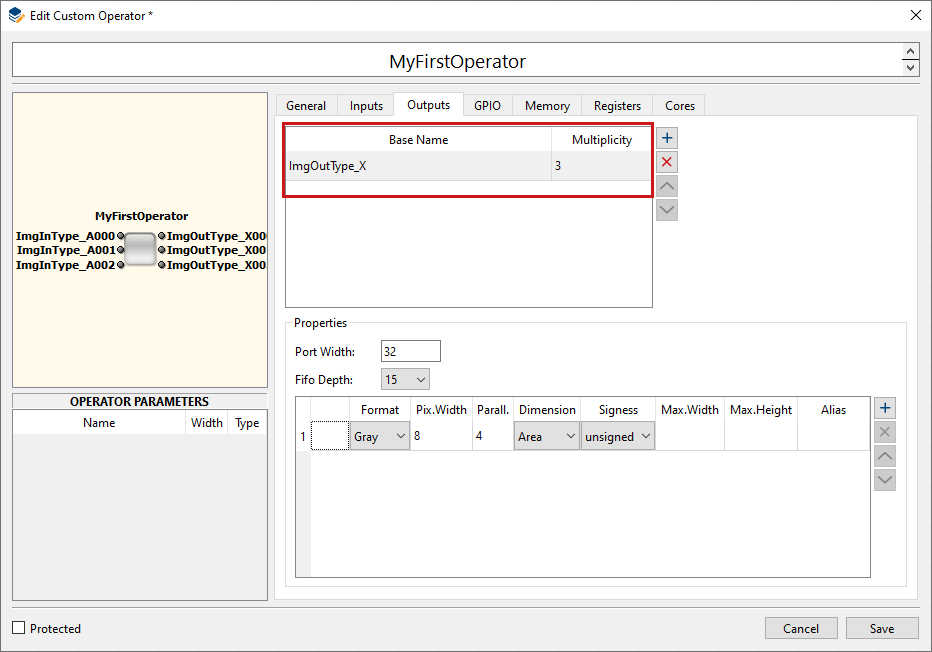
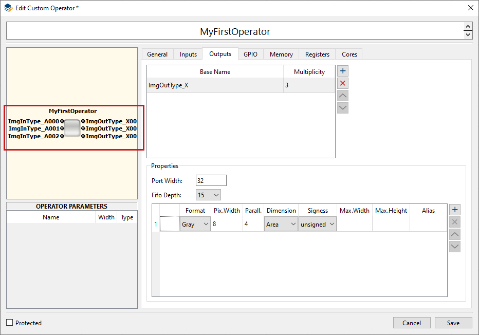
Immediately, the operator depiction in the program window displays the entered array of ImgOut ports:
-
In the panel, you specify the properties of the protocols that are supported by this ImgOut port.
Under , specify the width of the ImgOut port.
-
Under , specify the depth of the buffer FIFO for output data which at least needs to be provided by the VA core. The value must be a power of two minus 1 between 15 and 1023.
For an image interface port, you define a list of allowed protocols. A protocol can be described by the following properties:
-
Gray or color format (single or three data components with aggregated width N)
-
Flavor of color format (RGB, HSI, HSL, HSV, YUV, YCrCb, LAB, XYZ)
-
Pixel data bit width N = [1..64]
-
Parallelism P = {1,2,4,8,16,32,64}
-
2D (Aray), 1D (Line), or 0D (Raw)
-
Data type uint or int
-
Max. image dimensions
Implicitly it is assumed that the kernel size is 1x1.
The listed protocols are numbered starting from zero and therewith define an ID (in the image below visible in the left hand column of the table in the panel).
If you specify more than one protocol, you design the custom operator to support configuration of its input channel(s). In this case, several different protocols can be driven through a single port.
The user of your custom operator can select the protocol he wants to use on a specific ImgOut port. According to the selection made by the VA user, the corresponding ID will be output to the related custom operator port. This enables the custom operator to adapt its behavior to the selected protocol.
-
-
Under , specify the color format of the protocol.
The following color formats are allowed:
-
grayXxP: gray image with X bits per pixel and parallelism P
-
rgbYxP: color image with Y/3 bits per color component (red, green, blue) and parallelism P
-
hsiYxP: color image with Y/3 bits per color component (HSI color model) and parallelism P
-
hslYxP: color image with Y/3 bits per color component (HSL color model) and parallelism P
-
hsvYxP: color image with Y/3 bits per color component (HSV color model) and parallelism P
-
yuvYxP: color image with Y/3 bits per color component (YUV color model) and parallelism P
-
ycrcbYxP: color image with Y/3 bits per color component (YCrCb color model) and parallelism P
-
labYxP: color image with Y/3 bits per color component (LAB color model) and parallelism P
-
xyzYxP: color image with Y/3 bits per color component (XYZ color model) and parallelism P
-
-
Double-click in the field of column Pix.Width and specify the pixel data width for the specific format:
The value range of Pix.Width depends on your choice under :
Gray: The pixel data width (in the following referred to as X) is limited to 64 bit.
All color formats: The pixel data width (in the following referred to as Y) must be a multiple of 3 and is limited to 63 bit.
-
Double-click in the field of column and specify the parallelism for the specific format.
The parallelism defines the number of pixels which are contained in a single data word at the interface port. It must be chosen from following set of allowed values: P = {1, 2, 4, 8, 16, 32, 64}. Packing of image data into words of a given interface width N (specified under ) must follow certain rules:
-
The data of all P pixels must fit in a single word of length N. The data is stored LSB aligned which means that for a pixel width Z (Z=X for grey, Z=Y for color) data is distributed as follows: Pixel[0]->Bits[0..Z-1] .. Pixel[P-1]->Bits[(P-1)*Z..P*Z-1].
-
For RGB images the three color components are packed LSB aligned into a sub word [0..Y-1] in the following order: red uses the bits [0..Y/3-1 ], green the bits [Y/3..2*Y/3-1] and blue the bits [2*Y/3..3*Y/3-1].
-
For HSI color images the same rules than for RGB applies where H takes the role of red, S that of green and I the role of blue.
-
For HSL color images the same rules than for RGB applies where H takes the role of red, S that of green and L the role of blue.
-
For HSV color images the same rules than for RGB applies where H takes the role of red, S that of green and V the role of blue.
-
For YUV color images the same rules than for RGB applies where Y takes the role of red, U that of green and V the role of blue.
-
For YCrCb color images the same rules than for RGB applies where Y takes the role of red, Cr that of green and Cb the role of blue.
-
For LAB color images the same rules than for RGB applies where L takes the role of red, A that of green and B the role of blue.
-
For XYZ color images the same rules than for RGB applies where X takes the role of red, Y that of green and Z the role of blue.
-
-
Under , specify if the protocol supports 2D (Area), 1D (Line), or 0D (Raw) images.
-
: Using these optional fields you can define constraints for the image width and image height.
-
Repeat steps 6 to 10 to define as many protocols as you want the ImgOut port to support.
-
Repeat steps 1 to 11 to define as many ImgOut ports you want your custom operator to support.
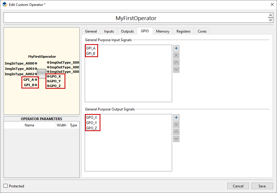
The General Purpose I/O interface allows connecting dedicated signal pins of the custom operator. Every GPIO port maps to a pin of the custom operator which is either an input or an output.
Bidirectional pins are not supported. In VisualApplets, the corresponding operator ports are of type SIGNAL.
-
Go to tab .
-
Add as many GPIs and GPOs as you want, using the ボタン
.
-
Double-click into the field to give a name to a specific GPI or GPO.
The defined GPIs and GPOs are immediately displayed in the depiction of the custom operator in the upper left hand panel of the program window:
|
Bidirectional Pins Not Supported |
|---|---|
|
The pins are either an input or an output. Bidirectional pins are not supported. |
A custom operator may be set up for accessing one or more banks of memory (DRAM, SRAM, …).
All memory ports have a FIFO-like interface for write and read commands. The FIFOs reside in the VA part of the custom operator, so that you only need to implement a flow control, but not the FIFO. The timing of forwarding the FIFO content to the memory controller attached to the custom operator is fully controlled by VisualApplets.
Under the tab, you can define that your operator gets access to external memory. You can specify up to 4 ports. You can specify the memory interface properties the operator needs.
|
Comply with Memory Layout of Target Platforms |
|---|---|
|
Keep in mind the memory layout of potential target platforms (on which the applets containing the custom operator will run). |
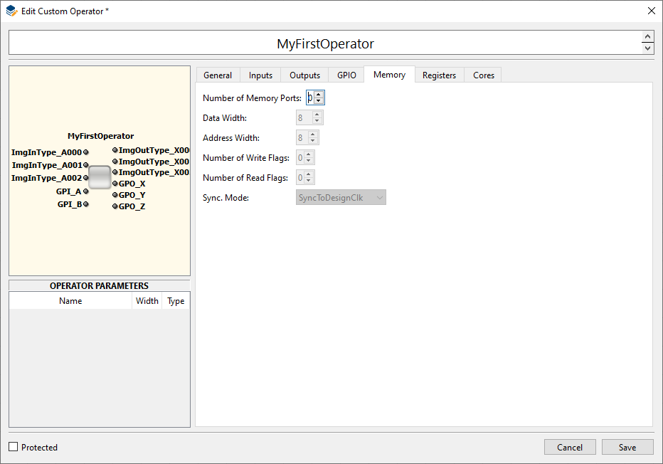
|
パラメーター名 |
タイプ |
説明 |
|---|---|---|
|
|
Integer |
Data width |
|
|
Integer |
Address width |
|
|
Integer |
Width of flag for marking write accesses. This parameter must be >= 1. |
|
|
Integer |
Width of flag for marking read accesses. This parameter must be >= 8. |
|
|
String |
This parameter signals the relation of the memory interface clock and the design clock. Following values are possible:
|
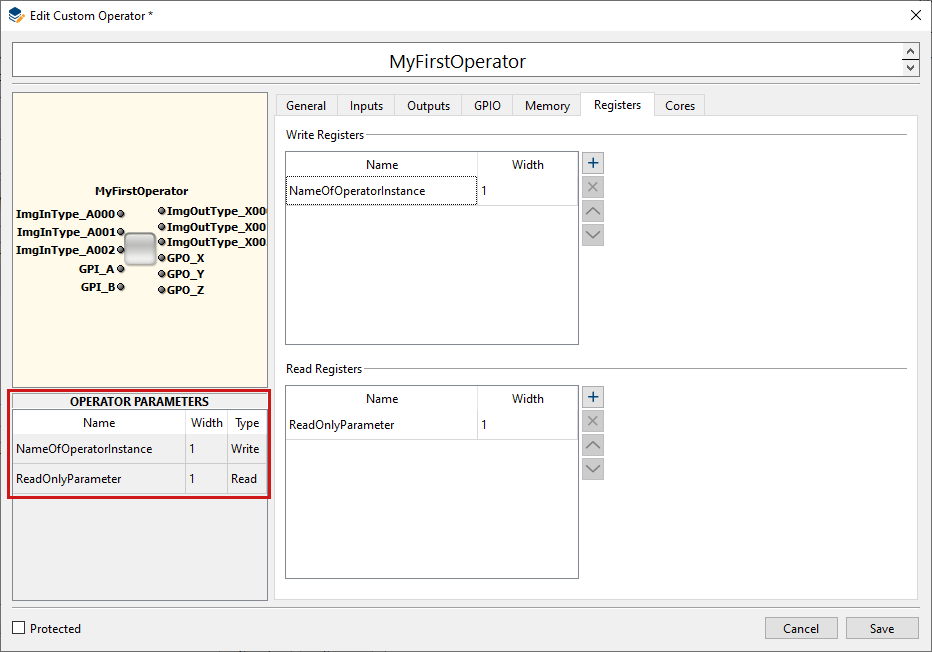
Under the tab, you can define the write and read registers your custom operator will provide. Each of this registers is accessed in VisualApplets via a dedicated operator parameter. (The parameter name is the same as the register name.)
-
Go to the tab.
-
Under , define the write registers you want your custom operator to have.
-
Define a specific width for each write register.
-
Under , define the read register you want your custom operator to have.
-
Define a specific width for each read register.
The related operator parameters are immediately displayed in the left hand lower panel of the dialog window:
-
Click
After you have entered all details as described in section 'Defining an Individual Custom Operator via GUI', you are ready for the actual VHDL coding. First of all, you need VisualApplets to generate the VHDL black box and test bench.
To trigger VHDL black box and test bench generation:
-
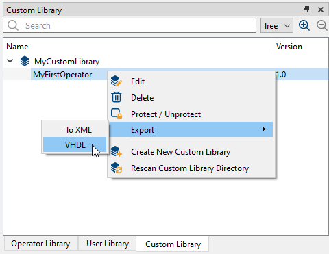
In the panel of the VisualApplets program window, go to the tab.
-
Open the custom library and select the custom operator you want to implement.
-
Right-click on the operator name, and from the sub menu, select → .
-
Specify the folder where you want the created VHDL files to be stored.
Now, the generation starts. After successful generation, a confirmation dialog opens up. Click to confirm.
You find all generated files in the folder you specified.
The generated black box provides all ports you specified via the GUI (see 'Defining an Individual Custom Operator via GUI').
In this chapter, you find a detailed description of how these ports look like in the generated VHDL black box.
VisualApplets supports two clock domains. There is a base design clock and one derived
clock which is in phase with that clock and has double frequency. Accordingly, there are two
clock inputs to the custom operator. Additionally, there is a Reset and
Enable input as described above.
|
ポート |
Direction |
Width |
説明 |
|---|---|---|---|
|
|
In |
1 |
Base design clock |
|
|
In |
1 |
Clock sync. to |
|
|
In |
1 |
Reset of operator |
|
|
In |
1 |
Enable processing |
The definition of write register ports as described in section 'Defining an Individual Custom Operator via GUI' leads to an interface as
follows where PORTID is the register name and
PORTIDWidth is the defined register width.
|
ポート |
Direction |
Width |
説明 |
|---|---|---|---|
|
|
In |
PORTID |
Register data |
|
|
In |
1 |
Signal write access |
The definition of read register ports as described in 'Defining the Registers of the Custom Operator' leads to the following interface, accordingly:
|
ポート |
Direction |
Width |
説明 |
|---|---|---|---|
|
|
Out |
PORTID |
Register data |
|
|
In |
1 |
Signal read access |
For communication of data between the VisualApplets core and a custom operator, image communication ports as described in 'Defining the Image Input Ports' may be configured. Communication is done via a simple FIFO interface and an additional format identifier port.
An ImgIn channel for transferring data from the VisualApplets core to a custom operator leads to an interface as follows where PORTID is the name of the corresponding port type name and X is a port number for differentiating several ports of the same kind:
|
ポート |
Direction |
Width |
説明 |
|---|---|---|---|
|
|
In |
PORTID |
Data entering the custom operator |
|
|
Out |
1 |
Accept input data |
|
|
In |
1 |
Signal end of line. If this flag is activated data doesn’t contain pixel values. |
|
|
In |
1 |
Signal end of frame. If this flag is activated data doesn’t contain pixel values. This flag is only asserted when end of line is signaled as well. |
|
|
In |
1 |
Buffer FIFO is empty |
|
|
In |
|
Number of words in buffer FIFO. This signal can be used to generate FIFO
flags like |
|
|
In |
|
Predefined parameter which notifies about the current image data format. N is the number of image formats specified for this port. |
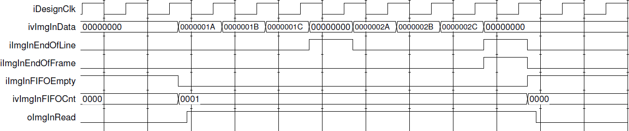
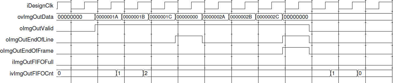
The figure below illustrates the data flow at an ImgIn port. The port name component PORTIDX has been substituted by ImgIn. The waveform shows the input of a two dimensional frame of size 3x2.
When the ImgIn port is part of several O-synchronous input ports, all of them must consume the FIFO data simultaneously. In that case the FIFO fill level of all ports will exactly match so the operator only needs to implement flow control according to the fill level of one out of several O- synchronous inputs.
An ImgOut channel for transferring data from a custom operator to the VisualApplets core leads to an interface as follows where PORTID is the name of the corresponding port type name and X is a port number for differentiating several ports of the same kind:
|
ポート |
Direction |
Width |
説明 |
|---|---|---|---|
|
|
Out |
PORTID |
Output data |
|
|
Out |
1 |
Output data valid |
|
|
Out |
1 |
Signal current write access as end of line notification. Write data is then not interpreted as pixel data. |
|
|
Out |
1 |
Signal current write access as end of frame notification. Write data is then not interpreted as pixel data. This flag needs to be correlated with an end of line strobe at the same time. |
|
|
In |
1 |
Buffer FIFO is full, no further data is accepted |
|
|
In |
|
Number of words in buffer FIFO. This signal can be used to generate FIFO
flags like |
|
|
In |
|
Predefined parameter which notifies about the current image data format. N is the number of image formats specified for this port. |
The figure below illustrates the data flow at an ImgOut port. The waveform shows the output of a two dimensional frame of size 3x2. When the ImgOut port is part of several O-synchronous output ports all of them must emit data simultaneously.
A custom operator may be set up for having up to four memory ports. The I/O ports of the generated interface get a suffix X where X is the index of the memory port.
|
名前 |
Direction |
Width |
説明 |
|---|---|---|---|
|
|
Out |
|
Write data output to memory via VisualApplets core |
|
|
Out |
|
Write flag output |
|
|
Out |
|
Write address |
|
|
Out |
1 |
Emit write command |
|
|
Out |
1 |
Request priority for this write port |
|
|
In |
1 |
Only single further write command may be accepted |
|
|
In |
1 |
No write command is accepted as concerning FIFO is full |
|
|
In |
1 |
FIFO for write commands is empty |
|
|
In |
4 |
Number of buffered write commands |
|
|
In |
|
Write flag output from the VisualApplets core |
|
|
In |
1 |
Write flag input valid – signals that |
|
|
Out |
|
Read flag |
|
|
Out |
|
Read address |
|
|
Out |
1 |
Emit read command |
|
|
Out |
1 |
Request priority for this read port |
|
|
In |
1 |
Only single further read command may be accepted |
|
|
In |
1 |
No read command is accepted as concerning FIFO is full |
|
|
In |
1 |
FIFO for read commands is empty |
|
|
In |
4 |
Number of buffered read commands |
|
|
In |
|
Read flag input – only valid when |
|
|
In |
|
Read data input |
|
|
In |
1 |
Read data valid |
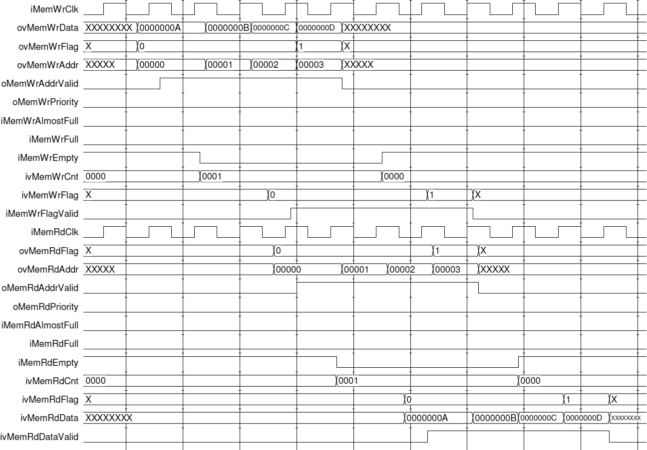
The figure above illustrates the waveform of the memory interface protocol.
Any GPIO input or output signal which has been defined in the interface description of the custom operator (section 'Defining an Individual Custom Operator via GUI') has a corresponding input or output port in the resulting operator interface. The following ports will be created when the general purpose pins are declared:
-
iSig_NAME for a GPIO input signal called NAME. -
oSig_NAME for a GPIO output signal called NAME.
For emulating a VisualApplets design which contains a custom operator module, VisualApplets creates a simulation test bench for the interfaces connecting to the custom operator.
Each interface port is emulated independently, driven by File I/O. The simulation entity shall consist of following elements:
-
Emulation of register access. According to a stimuli file a set of registers can be written and read.
-
Emulator for frame source connected to ports of type ImgIn. Stimulated by file these kinds of modules output frame data to ImgIn.
-
Emulator for frame sink connected to ports of type ImgOut. This kind of module emulates an operator which is connected to ImgOut. The module writes the received data to file.
-
Memory port emulator.
-
GPIO emulator. Each GPIO signal for input is driven by a signal generator which is configured by a file. Each GPIO signal output is monitored and changes of the signal are written to a report file.
For RTL level simulation, VisualApplets creates a VHDL file containing a package with
the name CustomOperator_<OPERATORNAME> where
<OPERATORNAME> is the given operator name.
This package contains the components <OPERATORNAME> and
<OPERATORNAME>_TB where the latter is a test bench of the
interface between the VisualApplets design and the custom operator. The following shows the
resulting code for a simple custom operator called RegExample
consisting only of a read and write register port (Ctrl and Status), each 4 bit wide:
component
RegExample port(
  iDesignClk: in std_logic := '0';
  iDesignClk2x: in std_logic := '0';
  iReset: in std_logic := '0';
  iEnable: in std_logic := '0';
  ivReg_Ctrl_D: in std_logic_vector(3 downto 0);
  iReg_Ctrl_Wr: in std_logic;
  ovReg_Status_D: out std_logic_vector(3 downto 0);
  iReg_Status_Rd: in std_logic
);
end component;

component
RegExample_TB generic(
  DesignClkPeriod: time := 16 ns;
  Register_StimuliFileName: string := ""
);
end component;
The test bench creates an instance of the custom operator and connects protocol emulation modules to each interface ports. The following sections describe the different kinds of emulators, how they may be controlled via stimuli files, and how output files are generated.
The generated test bench implements an emulator for a register access interface. The
emulator is configured for addressing a design with a single process. Addresses of write and
read registers start from 0x4 where addresses for registers are counted up with an increment
of 1 according to the sequence of the register interface ports in the given custom operator
component (like the above example component RegExample). Register
addresses for reading and writing are counted independently. The emulator is driven by a
text file which is set by the entity parameter
Register_StimuliFileName as provided in the above VHDL code.
The following commands may be present in the stimuli file:
|
コマンド |
説明 |
|---|---|
|
|
Rest of line is comment |
|
|
Emulate global reset |
|
|
Emulate process reset. This command has the following syntax: |
|
|
Enable process. The syntax is as follows: |
|
|
Wait for a number of clock cycles. The syntax is as follows, |
|
|
Write to register: |
|
|
Read from register: |
After the last parameter of any command, a comment may be added preceded by “#”.
The following code is an example stimuli file which accesses the registers according to
the above given test bench RegExample_TB:
REM ************************************************************
REM Command formats:
REM GRS	-> Global reset
REM GEN <value>	-> Set global enable to <value>
REM PRS <procID>	-> Reset process <procID> (0 .. F) REM PEN <procID> <value>
  -> Set enable of process <procID> to
<value>
REM WCK <clk_ticks>	-> Wait for <clk_ticks> clock cycles REM WRR <wrRegAddr> <value>
  -> Write <value> to register <wrRegAddr> REM RDR <rdRegAddr>	-> Read from register <rdRegAddr>
REM ************************************************************

WCK	0004		#	wait for 4 clock cycles
GRS			#	global reset
GEN	1		#	set global enable
WCK	0001		#	wait for 1 clock tick
PRS	0		#	reset process 0
PEN	0 1		#	set enable of process 0
WCK	0002		#	wait for 2 clock ticks
WRR	0004	0000000A	#	write 0xA to address 0x4
WCK	0002		#	wait for 2 clock ticks
RDR	0004		#	read from address 0x4
WCK	FFFF
The emulation of image communication interfaces of type ImgIn is
driven by a stimuli file providing information about the sequence of data which enters the
custom operator. For any present ImgIn port the test bench has a
generic <PORTIDX>_StimuliFileName where <PORTIDX> is the name of the corresponding
image input port type followed by the port number. Each line within the given file must
follow the syntax:
<Command> <Data> <EndOfLine> <EndOfFrame> <DataValid>
where <Command> is a three letter command, <Data> provides an hexadecimal data
word, and the three remaining parameters correspond to the image protocol flags.
The following table describes the available commands:
|
コマンド |
説明 |
|---|---|
|
|
Data command. This command provides data which will become input at the port
|
|
|
Wait command. The parameter |
|
|
Set FID input. The parameter |
To any command line a comment may be added, preceded by “#”.
The following code is an example stimuli file which causes the input of an 3x2-image:
FID	00000001	0	0	0 #Format: Cmd Data(hex) EndOfLine EndOfFrame DataValid
DAT	00000000	0	0	0
DAT	0000001a	0	0	1
DAT	0000001b	0	0	1
DAT	0000001c	0	0	1
DAT	00000000	1	0	1
WCK	00000004	0	0	0
DAT	0000002a	0	0	1
DAT	0000002b	0	0	1

DAT	0000002c	0	0	1
DAT	00000000	1	1	1
WCK	0000FFFF	0	0	0
The emulation of image communication interfaces of type ImgOut is
driven by a stimuli file where information is provided about the sequence of FID states. For
any present ImgOut port the VA_Design_Emulator entity has a generic
<PORTIDX>_StimuliFileName where
<PORTIDX> is the name of the corresponding image output port
type followed by the port number. The syntax is exactly the same as in the case of the
stimuli for ImgIn interfaces except that no DAT command is available. A
simple stimuli file may look like:
WCK 00000010 0 0 0    #Format: Command Data(hex)
FID 00000001 0 0 0
WCK 0000FFFF 0 0 0
The parameters
<EndOfLine>,<EndOfFrame> and
<DataValid> are actually meaningless.
The ImgOut interface emulator present in the generated test bench
writes the received data to file. For that purpose the test bench entity has a generic
<PORTIDX>_DumpFileName. During simulation a file with the
given name is created and the data is written using DAT and
WCK commands in a format, which exactly corresponds to the stimuli file
format for an ImgIn interface emulator.
When the custom operator implements an interface to memory the test bench connects a memory emulation module to the corresponding interface ports. The custom operator may not rely on a certain timing of the memory interface (like time until read data is returned) as this is fully controlled by VisualApplets and may vary between platforms and even between different designs.
The emulation of dedicated input signals is done for each signal independently, driven
by a stimuli file. There information is provided about the sequence of signal states. The
stimuli file may consist of a number of commands which are described below. For any present
output signal port the test bench entity has a generic
iSig_<NAME>_StimuliFileName where
<NAME> is the concerning port name.
The following table describes the available commands:
|
コマンド |
説明 |
|---|---|
|
|
Set signal. This command provides the signal state to which the output at the
port |
|
|
Wait command. It has the syntax: |
|
|
Restart from begin. The command interpreter will start again from the first line of the stimuli file. This command does not have any parameters. The command will execute the first command of the file at the same clock tick allowing assembling a loop without a gap. |
|
|
Stop at current state. The command interpreter will stop and the current signal state will be held constant until end of simulation. This command does not have any parameters. |
To any command line a comment may be added, preceded by “#”.
The following code is an example stimuli file which causes the custom operator input
signal toggling being low for 5 clock cycles and high for 7 clock cycles (synchronous to
iDesignClk):
SET 0	   # deassert output
WCK 0004	# wait for 4 clock cycles
SET 1	   # assert output
WCK 0006	# wait for 6 clock cycles
RST	     # restart from begin
Dedicated output signals are monitored writing a dump file
oSig_<NAME>_DumpFileName where
<NAME> is the concerning port name. The file is composed of SET
and WCK commands exactly corresponding to the commands of the stimuli file for an dedicated
input signal.
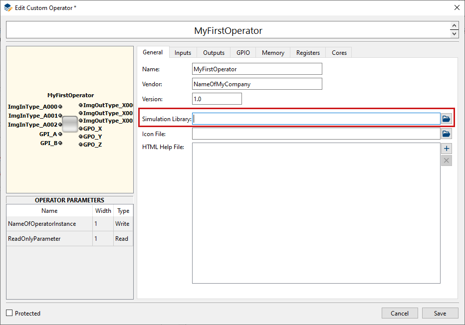
The high-level simulation component must be provided for fully integrating a custom operator to VisualApplets. The high-level simulation component needs to be compiled to a dynamic link library with a predefined set of exported C-Functions. You add this file to the operator specification under tab → :
For High-level simulation within VisualApplets the following function must be exported,
int SimulateOPNAME (va_custom_op_sim_handle simHandle)
where OPNAME is the name of the custom operator.
High-level simulation must be done according to following requirements:
-
Frame based simulation - On each image input port it can be queried whether one or more frames are available. If all ports which are required for starting simulation are able to provide a frame then the concerning output frames need to be computed and emitted via calls of appropriate functions. For one dimensional image data the data stream is automatically split into frames and simulated just like 2D-data.
-
Bit accurate simulation – The calculation of resulting frames must be bit accurate, i.e. the output data must be exactly equal to the data generated by the hardware implementation.
-
Keeping consistency of flow – When operator input ports are synchronous to each other input images must be fetched accordingly. When several outputs are defined images must be output simultaneously. For the simulation function this means that when a frame is output to one output link it must also output a frame to all other output links before the simulation function is returning.
As the behavior of the operator typically depends on the set of operator parameters these parameters may be queried via the following interface:
|
Nr. |
機能 |
説明 |
|---|---|---|
|
1 |
|
Get value of operator parameter. |
Several functions are provided by VisualApplets for getting, generating and storing image data for the custom operator:
|
Nr. |
機能 |
説明 |
|---|---|---|
|
1 |
|
Get image available at an ImgIn port. |
|
2 |
|
Output image to ImgOut port. |
|
3 |
|
Query whether ImgIn port may deliver an image. |
|
4 |
|
Query whether ImgOut port may take an image. |
|
5 |
|
Create new image. |
|
6 |
|
Delete image. |
|
7 |
|
Store image in local storage of operator instance providing a name whereby the image may later be referenced. |
|
8 |
|
Query number of images stored within operator instance. |
|
9 |
|
Get stored image by index. |
|
10 |
|
Get name of stored image by index. |
|
11 |
|
Get stored image by name. |
|
12 |
|
Create new image format handle which becomes initialized by the format associated with the given port. |
|
13 |
|
Create new image format which is a copy of given format. |
|
14 |
|
Delete image format handle created earlier. |
For manipulating images via image handles the following functions are available:
|
Nr. |
機能 |
説明 |
|---|---|---|
|
1 |
|
Get image format. |
|
2 |
|
Set property of frame (e.g. height). |
|
3 |
|
Get property of frame. |
|
4 |
|
Set pixel component value |
|
5 |
|
Get pixel component value |
|
6 |
|
Set individual length of a line. |
|
7 |
|
Get length of individual line. |
Image formats may be manipulated via the following functions:
|
Nr. |
機能 |
説明 |
|---|---|---|
|
1 |
|
Set image format property (e.g. maximum width). |
|
2 |
|
Get image format property. |
The simulation function may inject an status message (i.e., error message) into the VisualApplets simulation system using the following functions:
|
Nr. |
機能 |
説明 |
|---|---|---|
|
1 |
|
Create status message. |
|
2 |
|
Set property of status message (like severity). |
|
3 |
|
Submit the status message to the simulation engine. |
For querying information and configuring parameters data must be exchanged through the
software interface. To keep the interface functions simple but providing a type save interface
an abstraction mechanism for data is implemented. Whenever data of different types needs to be
communicated, a data structure called va_data is used, containing a
reference to the data and information about the underlying data type. This data structure is
created by the user but configured by dedicated functions listed below. The following table
shows the data types which are handled by this method:
|
Data Type |
説明 |
|---|---|
|
|
enum entry given as 32-Bit integer |
|
|
32-Bit signed integer |
|
|
32-Bit unsigned integer |
|
|
64-Bit signed integer |
|
|
64-Bit unsigned integer |
|
|
Floating-point number, double precision |
|
|
Array of 32-Bit signed integer numbers |
|
|
Array of 32-Bit unsigned integer numbers |
|
|
Array of 64-Bit signed integer numbers |
|
|
Array of 64-Bit unsigned integer numbers |
|
|
Array of double numbers |
|
|
String given as |
Configuring an earlier created va_data structure
(vaData) for setting up data communication is done via the following
functions:
va_data* va_data_enum(va_data* vaData, int32_t *data)
va_data* va_data_int32(va_data* vaData, int32_t *data)
va_data* va_data_uint32(va_data* vaData, uint32_t *data)
va_data* va_data_int64(va_data* vaData, int64_t *data)
va_data* va_data_uint64(va_data* vaData, uint64_t *data)
va_data* va_data_double(va_data* vaData, double *data)
va_data* va_data_int32_array(va_data* vaData, int32_t *data, size_t elementCount)
va_data* va_data_uint32_array (va_data* vaData, uint32_t *data, size_t elementCount)
va_data* va_data_int64_array (va_data* vaData, int64_t *data, size_t elementCount)
va_data* va_data_uint64_array (va_data* vaData, uint64_t *data, size_t elementCount)
va_data* va_data_double_array (va_data* vaData, double *data, size_t elementCount)
va_data* va_data_string(va_data* vaData, char data*, size_t strSize)
va_data* va_data_const_string(va_data* vaData, const char **data)
For strings there are two options how strings are communicated:
-
Providing a char array via
va_data_string(). Then queried string data will be copied to that array. -
Providing a pointer to
const char*. Then a pointer to an internal string representation is returned when information of typeVA_STRINGis queried. When you use this approach check the livetime of the returned string.
Example Code: The following example shows code for querying the image width.
uint32_t imgWidth;
va_data
va_imgWidth;
va_data_double(&va_imgWidth,&imgWidth);

vaSi_Image_GetProperty(imageHandle, "Width", &va_imgWidth);
After that the variable imgWidth will contain the requested
information.
The following gives a detailed description of parameters and returned values for the specified simulation interface functions.
|
機能 |
|
|---|---|
|
Syntax |
|
|
Parameter 1 |
Simulation handle provided to the operator simulation function. |
|
Parameter 2 |
Name of parameter. |
|
Parameter 3 |
Return parameter for queried value. |
|
説明 |
Returns the value of the parameter with the given name. |
|
Return value |
0 : Value is queried data <0: Cannot query parameter |
|
機能 |
|
|---|---|
|
Syntax |
|
|
Parameter 1 |
Simulation handle provided to the operator simulation function. |
|
Parameter 2 |
Name of operator port. |
|
Parameter 3 |
Return parameter for image handle. |
|
説明 |
Take an image which enters the operator at the given port and return a handle
referencing that image. Before returning from the simulation function this image
must either be stored by calling |
|
Return value |
0: OK <0 : Cannot get image |
|
機能 |
|
|---|---|
|
Syntax |
|
|
Parameter 1 |
Simulation handle provided to the operator simulation function. |
|
Parameter 2 |
Name of operator port. |
|
Parameter 3 |
Image handle. |
|
説明 |
Outputs image to the given port. |
|
Return value |
0 : Operation has been completed successfully <0: Cannot output image |
|
機能 |
|
|---|---|
|
Syntax |
|
|
Parameter 1 |
Simulation handle provided to the operator simulation function. |
|
Parameter 2 |
Name of operator input port. |
|
説明 |
Returns whether there is an input image available at the port with the given name. |
|
Return value |
true : Image is available false : No image available |
|
機能 |
|
|---|---|
|
Syntax |
|
|
Parameter 1 |
Simulation handle provided to the operator simulation function. |
|
Parameter 2 |
Name of operator output port. |
|
説明 |
Returns whether the output port with the given name may take an image. |
|
Return value |
true : Output ready for next image false : Output not ready for taking image |
|
機能 |
|
|---|---|
|
Syntax |
|
|
Parameter 1 |
Simulation handle provided to the operator simulation function. |
|
Parameter 2 |
Image format of the new image. |
|
Parameter 3 |
Return parameter for image handle. |
|
説明 |
Creates a blank image based on the format given by parameter 2. Before
returning from the simulation function this image must either be stored by calling
|
|
Return value |
0 : OK <0 : Could not create image |
|
機能 |
|
|---|---|
|
Syntax |
|
|
Parameter 1 |
Simulation handle provided to the operator simulation function. |
|
Parameter 2 |
Handle of image which shall be deleted. |
|
説明 |
Deletes image referenced by given image handle. |
|
Return value |
0 : Operation has been completed successfully <0: Error during deleting image |
|
機能 |
|
|---|---|
|
Syntax |
|
|
Parameter 1 |
Simulation handle provided to the operator simulation function. |
|
Parameter 2 |
Image handle. |
|
Parameter 3 |
Name as which the image shall be stored. The image may later be queried by this name. |
|
説明 |
Stores image in local storage of the operator simulation instance. |
|
Return value |
0 : Operation has been completed successfully |
|
機能 |
|
|---|---|
|
Syntax |
|
|
Parameter 1 |
Simulation handle provided to the operator simulation function. |
|
Parameter 2 |
Return parameter for image count. |
|
説明 |
Returns the number of images which are stored within the operator simulation instance. |
|
Return value |
0: OK <0: Can’t query information. |
|
機能 |
|
|---|---|
|
Syntax |
|
|
Parameter 1 |
Simulation handle provided to the operator simulation function. |
|
Parameter 2 |
Index within the array of stored images. |
|
Parameter 3 |
Return parameter for image handle. |
|
説明 |
Get image which has been stored before. The image is removed from the image
storage. Before returning from the simulation function this image must either be
stored again by calling |
|
Return value |
0 : OK <0 : Could not get image |
|
機能 |
|
|---|---|
|
Syntax |
|
|
Parameter 1 |
Simulation handle provided to the operator simulation function. |
|
Parameter 2 |
Index within the array of stored images. |
|
説明 |
Returns a string of the image name. |
|
Return value |
Not |
|
機能 |
|
|---|---|
|
Syntax |
|
|
Parameter 1 |
Simulation handle provided to the operator simulation function. |
|
Parameter 2 |
Name under which the image has been stored. |
|
Parameter 3 |
Return parameter for image handle. |
|
説明 |
Get image which has been stored before with the given storage name. The image
is removed from the image storage. Before returning from the simulation function
this image must either be stored again by calling
|
|
Return value |
0 : OK <0 : Could not get image |
|
機能 |
|
|---|---|
|
Syntax |
|
|
Parameter 1 |
Simulation handle provided to the operator simulation function. |
|
Parameter 2 |
Name of operator port. |
|
Parameter 3 |
Return pointer for format handle. |
|
説明 |
Creates a new image format object and returns a corresponding handle. The
format is initialized by the format of the port with the given name. Before
returning from the simulation function the format must become deleted by calling
|
|
Return value |
0 : OK <0 : Could not create format |
|
機能 |
|
|---|---|
|
Syntax |
|
|
Parameter 1 |
Simulation handle provided to the operator simulation function. |
|
Parameter 2 |
Handle of format which is being copied. |
|
Parameter 3 |
Return parameter for format handle. |
|
説明 |
Creates a new image format object and returns a corresponding handle. The
format is initialized by the provided format. Before returning from the simulation
function the format must become deleted by calling
|
|
Return value |
Not |
|
機能 |
|
|---|---|
|
Syntax |
|
|
Parameter 1 |
Simulation handle provided to the operator simulation function. |
|
Parameter 2 |
Handle of format which is being deleted. |
|
説明 |
Deletes the image format object referenced by the given format handle. |
|
Return value |
0: OK <0 : Could not delete format |
|
機能 |
|
|---|---|
|
Syntax |
|
|
Parameter 1 |
Image handle. |
|
Parameter 2 |
Handle of earlier created format which will be set to format of image. |
|
説明 |
Queries the format of the image referenced by the image handle. |
|
Return value |
0 : Operation has been completed successfully <0: Cannot query format |
|
機能 |
|
|---|---|
|
Syntax |
|
|
Parameter 1 |
Image handle. |
|
Parameter 2 |
String identifying the property which shall be set. |
|
Parameter 3 |
Pointer to data structure which will be used for setting the new property. |
|
説明 |
Set property of the image referenced by the image handle. Following properties may be set via this function:
|
|
Return value |
0 : Property has been set successfully |
|
機能 |
|
|---|---|
|
Syntax |
|
|
Parameter 1 |
Image handle. |
|
Parameter 2 |
Enum value identifying the property which shall be queried. |
|
Parameter 3 |
Pointer to data structure which will be used for data communication. |
|
説明 |
Queries the properties of the image referenced by the image handle. Following properties are available:
|
|
Return value |
0 : Property has been queried successfully |
|
機能 |
|
|---|---|
|
Syntax |
|
|
Parameter 1 |
Image handle. |
|
Parameter 2 |
Line number. |
|
Parameter 3 |
Line length. |
|
説明 |
Sets the length of the referenced line to an individual value which may differ to the overall image width (not exceeding the maximum image width defined by the image format). |
|
Return value |
0 : Operation has been completed successfully <0: Cannot set line length to the given value |
|
機能 |
|
|---|---|
|
Syntax |
|
|
Parameter 1 |
Image handle. |
|
Parameter 2 |
Line number. |
|
Parameter 3 |
Return parameter for line length. |
|
説明 |
Returns the length of the referenced line. |
|
Return value |
0: OK <0: Cannot query line length |
|
機能 |
|
|---|---|
|
Syntax |
|
|
Parameter 1 |
Image handle. |
|
Parameter 2 |
Position within the frame. |
|
Parameter 3 |
Component index. |
|
Parameter 4 |
Pixel component value. |
|
説明 |
Sets the corresponding pixel component to the given value. |
|
Return value |
0 : Operation has been completed successfully <0: Error setting the pixel component value |
|
機能 |
|
|---|---|
|
Syntax |
|
|
Parameter 1 |
Image handle. |
|
Parameter 2 |
Position within the frame. |
|
Parameter 3 |
Component index. |
|
Parameter 4 |
Return parameter for pixel component value |
|
説明 |
Returns the corresponding pixel component value. |
|
Return value |
0 : Operation has been completed successfully <0: Error getting the pixel component value |
|
機能 |
|
|---|---|
|
Syntax |
|
|
Parameter 1 |
Image format handle. |
|
Parameter 2 |
Enum value identifying the property which shall be set. |
|
Parameter 3 |
Pointer to data structure which holds the new property. |
|
説明 |
Sets properties of the image format referenced by the handle. Following properties may be set via this function:
|
|
Return value |
0 : Property has been set successfully
|
|
機能 |
|
|---|---|
|
Syntax |
|
|
Parameter 1 |
Image format handle. |
|
Parameter 2 |
Enum value identifying the property which shall be queried. |
|
Parameter 3 |
Pointer to data structure which will be overwritten by the queried property. |
|
説明 |
Queries properties of the image format referenced by the handle. The properties
which may be queried are identical to the ones which can be set through the function
|
|
Return value |
0 : Property has been queried successfully
|
|
機能 |
|
|---|---|
|
Syntax |
|
|
Parameter 1 |
Simulation handle. |
|
Parameter 2 |
Return parameter for created error message. |
|
説明 |
Create a status message which may be submitted to the simulation engine. |
|
Return value |
0 : OK <0: Can’t create message |
|
機能 |
|
|---|---|
|
Syntax |
|
|
Parameter 1 |
Simulation handle. |
|
Parameter 2 |
Status message handle. |
|
Parameter 3 |
Name of property which shall be set. |
|
Parameter 4 |
New property value |
|
説明 |
Alter status message property. Following properties may be set via this function:
|
|
機能 |
|
|---|---|
|
Syntax |
|
|
Parameter 1 |
Simulation handle. |
|
Parameter 2 |
Handle of status message which shall be submitted. |
|
説明 |
Submitted status message to the simulation engine. |
|
Return value |
0 : OK <0: Can’t submit message |
Documentation of the operator should be provided as an HTML file. When available, all files which make up the documentation need to be specified under tab → :
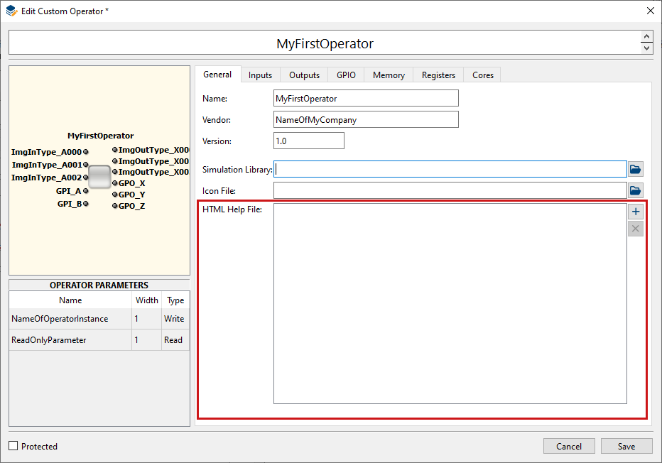
The first file that is specified is interpreted to be the starting point of the
operator’s documentation. The naming convention for this file is:
<NameOfCustomOperator>.htm.
Make sure you provide a CSS file. Make sure you also provide all related image files.
You can use the operator template provided in the VisualApplets install directory in
subdirectory Examples/CustomLibrary/OperatorTemplate.
When you have wrapped your HDL code so that its interface matches the generated black box, you need to proceed some last steps for completing your custom operator:
-
Create a netlist out of your implementation.
Set Add IO Buffer = NOWhen creating the netlist, make sure that your synthesis tool doesn’t automatically add IO buffers. In case you use XST for netlist synthesis you set
Add IO Buffer = NOOtherwise, the resulting NGC file will cause errors during the VisualApplets build flow.
Warnings During Netlist Generation When generating the net list, warnings may be output concerning unused IO Ports of the custom operator interface. Unused IO Ports are all ports that were generated according to your operator definition, but are not connected with your IP core. You may ignore these warnings.
Examples of this behavior are all custom operator examples you find in the
Examplesdirectory of your VisualApplets installation:\Examples\CustomLibrary -
If required, also define a constraints file (
*.ucfformat if you use Xilinx ISE,*.xdcformat if you use Xilinx Vivado). -
Optionally, set up the operator’s software interface as described in section 'Defining the Custom Operator’s Software Interface'.
-
Optionally, create the operator documentation as described in section 'Creating Custom Operator Documentation'.
Now, you need to complete the operator definition in VisualApplets. To do so, proceed as follows.
Required steps:
-
Go to the tab.
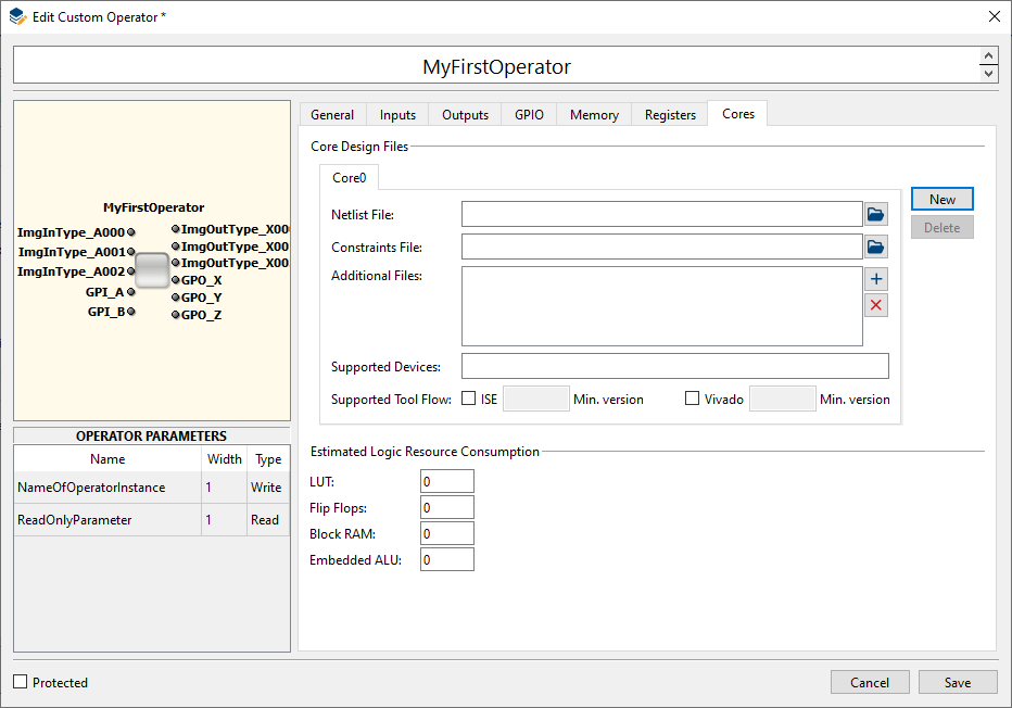
-
Specify the netlist file you generated.
-
Specify the constraints file if you defined constraints.
-
Specify the supported devices: The device name is the name of the FPGA type of the target platform. Please use exactly the same spelling as provided in the project info box of VisualApplets. If several FPGA types are supported, use a space separated list of names.
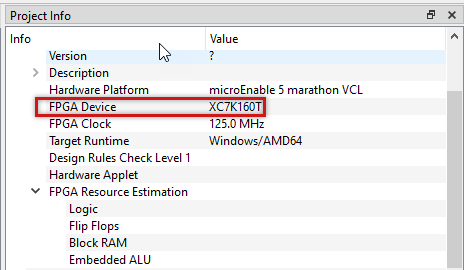
If a design uses the custom operator, but the FPGA on the target platform is not in this list, the DRC will report an error that the operator is not supported by the target platform.
-
Specify the supported Xilinx Tool(s). You can check the boxes for both ISE and Vivado. Netlists generated with ISE are usually also compatible with the Vivado build flow but you should check whether this is the case for your operator implementation. You need to define the minimal version number of the tool which supports the given netlist. Typically this would be the version which you used for creating the net list.
If a design uses the custom operator, but the specified tools are not used for building the design, the DRC will report an error that the operator is not supported by the target platform.
Defining Multiple Cores You can define multiple cores for the same custom operator. This will allow to use device and tool specific implementations of the custom operator so for different target platforms the appropriate implementation is chosen for building an applet.
Optional steps:
-
Optionally, enter the consumption of logic resources by the operator. Simply enter the values estimated by the Xilinx tools during generation of netlist.
-
Under the tab, specify the path to your simulation library (the custom operator’s software interface).
-
Under the tab, specify the path to the icon file. This is the file that contains the icon that will be used when your custom operator is displayed in VisualApplets.
-
Under the tab, specify all files that make up your custom operator documentation. Make sure you also provide a CSS file and all related image files.
-
If you want to protect your operator design: In the left bottom corner, activate the option . In the dialog that opens:
-
Make sure protection mode is activated.
-
Enter your password.
-
Click .
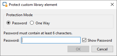
You can always protect your custom operator design also at a later point of time, using the context menu of the custom library element.
Protecting Options After protection has been enabled, the custom operator is made a “black box”. There are two ways to protect a custom operator design:
-
Protection via password: The custom operator design can afterwards be opened and edited via password. Users that do not have the password will not be able to see any details of the custom operator (black box).
-
Irreversible protection: If you select protection mode One-Way, the custom operator is made a black box forever and cannot be re-opened, not even by yourself.
"One-Way" protection is irreversible: If you select protection mode One Way (instead of Password), the custom library element can never be re-opened, not even by yourself. If you plan to enhance the element at a later point of time, make sure you select protection mode instead. Alternatively, you can save a copy of the element (as a hierarchical box or a non-protected operator) before enabling this protection mode.
-
-
Click .
Now, your new custom operator is ready for being used in designs.
A custom library with all contained operators is stored as one single
<LibaryName>.val or
<LibaryName>.vl file.
<LibaryName> is the name of the custom library.
This file can be distributed and directly applied in VisualApplets. It simply needs to be copied into the Custom Library directory which is specified in the VisualApplets settings ( → → →
-
Copy the new
<LibaryName>.valor<LibaryName>.vlfile to the Custom Library directory of your VisualApplets installation. -
Re-scan the custom library in the VisualApplets GUI: Right-click on the library name and from the sub menu select .
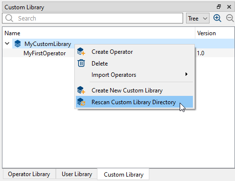
In the VisualApplets examples directory, you find a ready-to-use library called
CustomLibrary.vl
which contains all example operators.
When you make changes to a custom operator, these changes are not reflected in the designs where you already use the custom operator. Therefore, you need to update the custom operator instances in the designs.
-
Right-click on the operator.
-
From the sub-menu, select or .
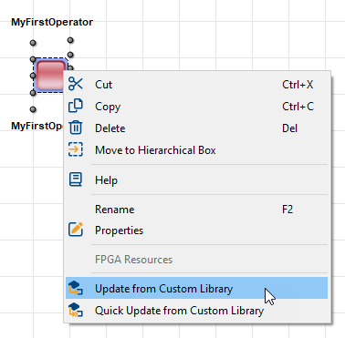
The update mechanism for Custom Libraries is exactly the same as for User Libraries.
You can import and export individual custom operators by importing/exporting the XML definition of the operator.
To import a custom operator:
-
Right-click on the custom library where you want to import the custom operator to.
-
From the sub-menu, select → .
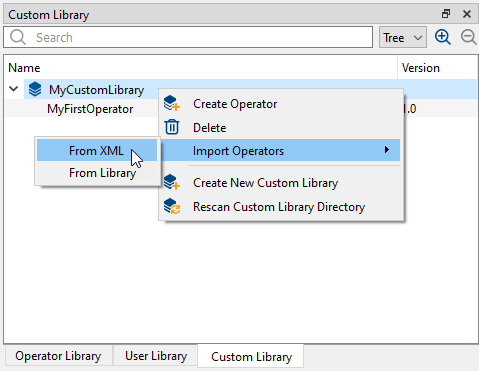
-
Specify the path to the custom operator’s XML definition and click .
Immediately, the dialog opens:
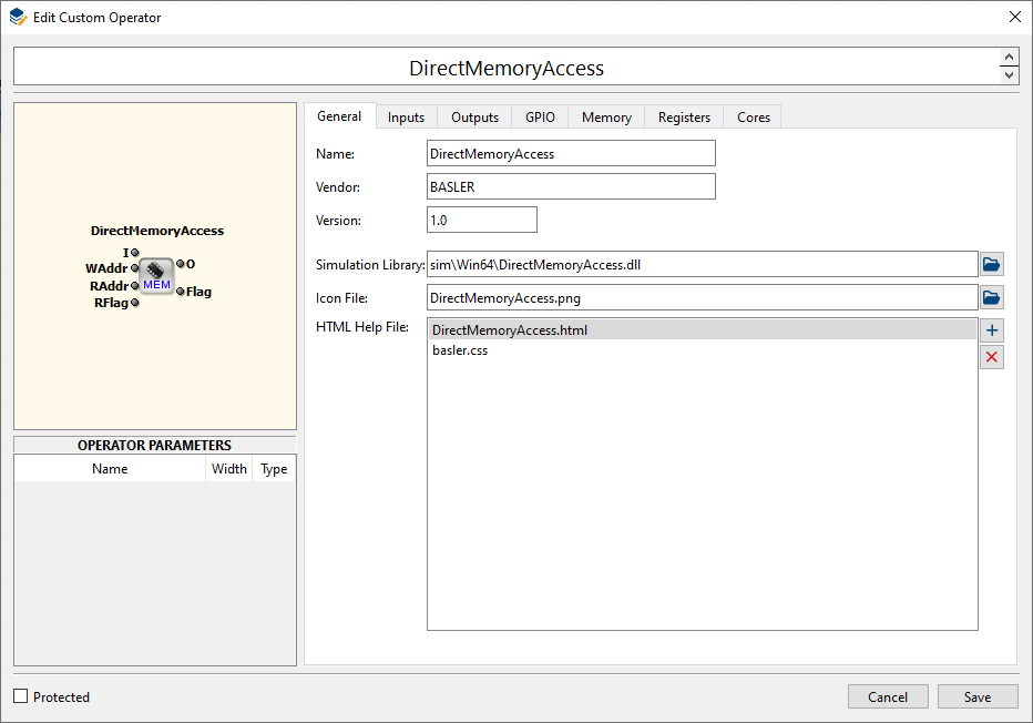
-
Click .
After saving, the imported operator is directly available in the custom library:
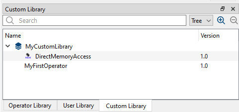
In the install directory, you find three completed custom operators which you can use as reference. You find the examples here:
\Examples\CustomLibrary
In the install directory, you find a custom operator template which you can use for defining your custom operators.
\Examples\CustomLibrary To use the custom operator template:
-
Right-click on the custom library where you want to create the new custom operator in.
-
From the sub-menu, select → .
-
Specify the path to the operator template.
-
Click .
Immediately, the dialog opens:
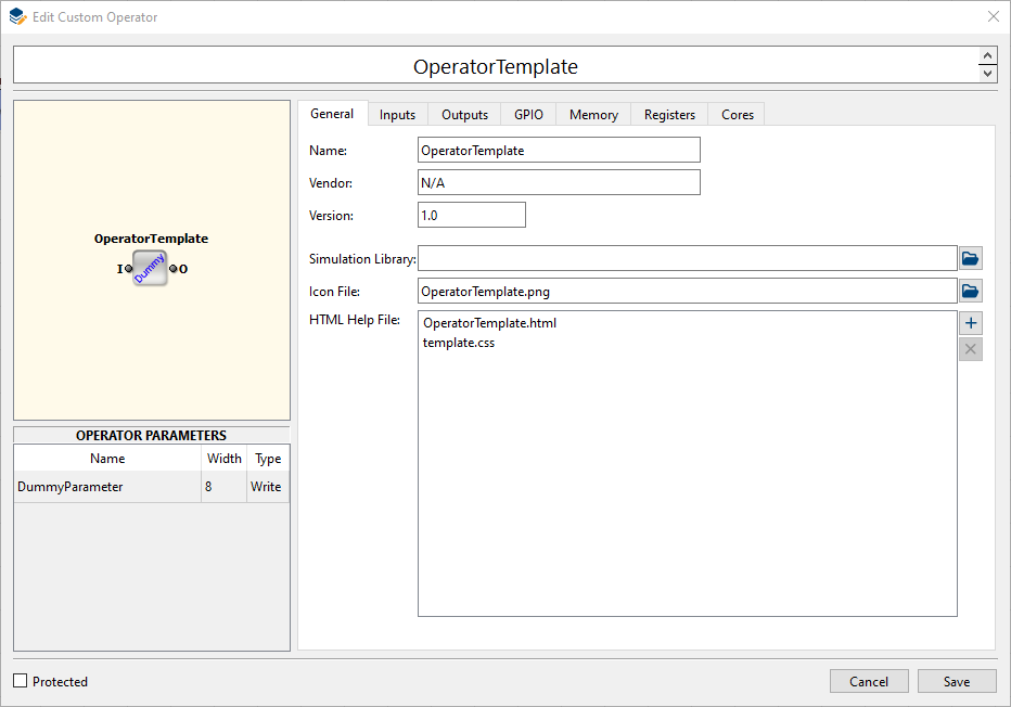
-
Give a name to your new custom operator and proceed as described in section 'Defining an Individual Custom Operator via GUI'.
The definition of a custom operator is stored in XML format. A concerning XML file can be exported from the operator library or an operator can be imported using an earlier exported XML file.
In the following, we describe the required parameters where the parameter name is related
to an XML tag with the same name. A parameter like ImgInInfo will
translate to an XML entry like:
<ImgInInfo> ImgInPortNames </ImgInInfo> where
ImgInPortNames is the value which in this case would be a sequence of
port names. The parameters are hierarchically ordered. In the following tables, lines with
gray background will notify the hierarchy position where the parameters are expected.
Simple parameter values can be of following types:
-
Choice: the allowed values are
YESorNO -
String: an ASCII string without whitespace
-
Integer
-
Floating-point
Some parameters are composed as a structure of values where arrays or records are
possible elements for structuring. Arrays are entered by a list of values separated by white
space where the values themselves may be structured. Records are entered by a scheme like
follows where RecordName is the record identifier,
attrX are the identifiers for the record entries and
attrXValue are the values:
<RecordName attr1=”attr1Value” .. attrN=”attrNValue”/>
An example would be providing a record called port with entries for
name and width:
<port name=”flag” width=”4”/>
The root tag of the XML format is Operator with an attribute
name where the custom operator name should be provided:
<Operator name=”XYZ”>
…
</Operator>
|
Comply with VHDL Naming Conventions |
|---|---|
|
When defining the operator name in the VA GUI, make sure you conform to the VHDL naming conventions. VHDL valid names are defined as follows: “A valid name for a port, signal, variable, entity name, architecture body, or similar object consists of a letter followed by any number of letters or numbers, without space. A valid name is also called a named identifier. VHDL is not case sensitive. However, an underscore may be used within a name, but may not begin or end the name. Two consecutive underscores are not permitted.” |
|
パラメーター名 |
タイプ |
説明 |
|---|---|---|
|
|
String |
Name of Vendor. |
|
|
String |
Version number of the operator. The value can be freely chosen and is intended for version identification by the user. |
|
|
Array of String |
List of core netlists for the operator. The first string must be
|
|
|
String |
Quoted name of file containing software library (dynamic link library) containing the high-level simulation model for the operator. |
|
|
String |
Quoted name of file containing the operator icon. |
|
|
Array of String |
List of quoted file names which contain help content (html + images). The first file is considered as the main HTML file. |
Table 7. Operator/Info
|
パラメーター名 |
タイプ |
説明 |
|---|---|---|
|
|
Array of String |
List of names of later defined info structures
( |
|
|
Array of String |
List of names of later defined info structures
( |
|
|
String |
String defining whether the inputs at the ImgIn ports are synchronous or asynchronous to each other. This string may either be “Sync” or “Async”. |
|
|
Array of String |
List of names of later defined info structures
( |
|
|
Array of String |
List of names of later defined info structures
( |
|
|
Array of String |
List of pin names for general purpose signal inputs. |
|
|
Array of String |
List of pin names for general purpose signal outputs. |
|
|
Array of String |
List of names of later defined info structures
( |
Table 8. Operator/IO
|
パラメーター名 |
タイプ |
説明 |
|---|---|---|
|
|
Integer |
Number of FPGA LUT elements consumed by the operator |
|
|
Integer |
Number of FPGA registers consumed by the operator |
|
|
Integer |
Number of block ram elements consumed by the operator |
|
|
Integer |
Number of embedded multipliers consumed by the operator |
Table 9. Operator/Properties
Image input port specification is done by following syntax within the configuration file:
<ImgIn name=”IMG_IN_IDENTIFIER”> Parameters </ImgIn>;
Here IMG_IN_IDENTIFIER is one of the image input port names which
have been provided in the above parameter Operator/IO/ImgInInfo. The
content Parameters is specifying the properties of the image interface
port:
|
パラメーター名 |
タイプ |
説明 |
|---|---|---|
|
|
Integer |
Width of the image data port |
|
|
Integer |
Depth of the buffer FIFO for input data which at least needs to be provided by the VA core. The value must be a power of two minus 1 between 15 and 1023. |
|
|
Array of Record |
List of image format records |
Table 10. Operator/ImgIn
The image format records have the following structure:
<ImgFormat name=”FORMAT” maxWidth=”X1” maxHeight=”Y1” alias=”NAME1”/>
The entry FORMAT is a String value for an image format coded by the
below discussed naming scheme for image formats. The attributes
maxWidth and maxHeight are optional and fix
the limits of image size. If they are not present, the image size constraints can be freely
chosen by the user within VisualApplets later on. The attribute alias
is optional as well and, if present, defines the name under which the format will be displayed
in the GUI.
Image output port specification is done by following syntax within the configuration file:
<ImgOut name=”IMG_OUT_IDENTIFIER”> Parameters </ImgOut>;
Here IMG_OUT_IDENTIFIER is one of the image output port names
which have been provided in the above parameter Operator/IO/ImgOutInfo.
The content Parameters is specifying the properties of the image
interface port:
|
パラメーター名 |
タイプ |
説明 |
|---|---|---|
|
|
Integer |
Width of the image data port |
|
|
Integer |
Depth of the buffer FIFO for output data which at least needs to be provided by the VA core. The value must be a power of two minus 1 between 15 and 1023. |
|
|
Array of Record |
List of image format records |
Table 11. Operator/ImgOut
Image formats are coded by the following naming scheme:
{BaseFormat}{BitsPerPixel}x{Parallelism}
Optionally there can be suffixes for image dimension and the notification of signed component data:
{BaseFormat}{BitsPerPixel}x{Parallelism}x{Dimension}{Sign}
The meaning of the dimension is as follows:
-
Dimension = 2– a two-dimensional image means that the image is structured both by end-of-line and end-of-frame markers. -
Dimension = 1– a one-dimensional image means that there are no end-of-frame markers which divide the incoming lines into frames.
When no dimension is specified a value of two is assumed. The suffix
{Sign} can be s for signed pixel components or
u for unsigned values where the default value is u
when no such suffix is provided. Supported color formats are rgb,
yuv, hsi, lab and
xyz.
Examples are:
-
gray8x4 – gray format with 8-bit pixel and parallelism 4
-
rgb24x2 – rgb color format with 3x8-bit pixel and parallelism 2
-
gray16x1 – gray format with 16-bit pixel, only single pixel in a data word
-
gray8x4x1 – one dimensional gray image with 8-bit per pixel and parallelism 4
-
gray16x1s – gray image with signed 16-bit components, only single pixel in a data word
Register input port specification is done by following syntax within the configuration file:
<RegIn name=”REG_IN_IDENTIFIER”> Parameters </RegIn>;
Here REG_IN_IDENTIFIER is one of the register input port names
which have been provided in the above parameter Operator/IO/RegInInfo.
The content Parameters is specifying the properties of the register
interface port:
Register output port specification is done by following syntax within the configuration file:
<RegOut name=”REG_OUT_IDENTIFIER”> Parameters </RegOut>;
Here REG_OUT_IDENTIFIER is one of the register output port names
which have been provided in the above parameter Operator/IO/RegOutInfo.
The content Parameters is specifying the properties of the register
interface port:
Memory interface specification is done by sections with following syntax within the configuration file:
<Mem name=”MEM_IDENTIFIER”> Parameters </MEM>
Here MEM_IDENTIFIER is one of the memory port names which have
been provided in the above described parameter Operator/IO/MemInfo. The
content Parameters is specifying the properties of the memory
interface:
|
パラメーター名 |
タイプ |
説明 |
|---|---|---|
|
|
Integer |
Data width |
|
|
Integer |
Address width |
|
|
Integer |
Width of flag for marking write accesses. This parameter must be >= 1. |
|
|
Integer |
Width of flag for marking read accesses. This parameter must be >= 8. |
|
|
Integer |
Width of port for communicating the number of available write commands |
|
|
Integer |
Width of port for communicating the number of available read commands |
|
|
String |
This parameter signals the relation of the memory interface clock and the design clock. Following values are possible:
|
Table 14. Operator/Mem
Specification of IP core netlists is done by sections with following syntax within the configuration file:
<Core name=”CORE_IDENTIFIER”> Parameters </Core>
Here Core_IDENTIFIER is one of the core names which have been
provided in the above described parameter Operator/Cores. The content
Parameters is specifying the properties of the IP core:
|
パラメーター名 |
タイプ |
説明 |
|---|---|---|
|
|
Array of String |
List of FPGA device names which are supported by the core (Example:
|
|
|
String |
Quoted UTF-8 encoded file name for the net list. |
|
|
String |
Quoted UTF-8 encoded file name for an optional constraints file. |
|
|
String |
Minimum version number of ISE tool flow which can use the given netlist
(Example: |
|
|
String |
Minimum version number of Vivado tool flow which can use the given netlist
(Example: |
Table 15. Operator/Core
