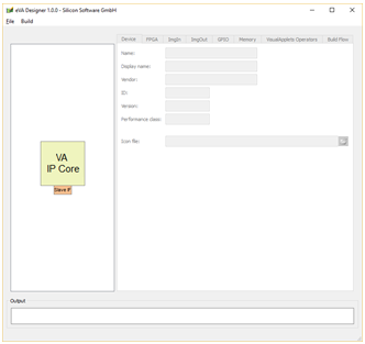
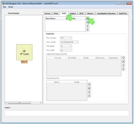
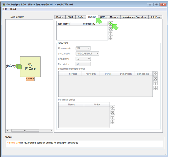
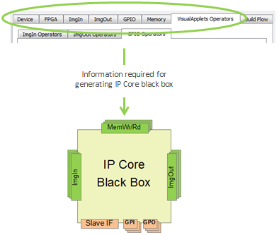
For defining the interfaces of the individual VA IP Core you want to use on your FPGA, you use the GUI tool . eVA Designer is part of the VisualApplets Embedder package. eVA Designer is installed together with VisualApplets. You can use eVA Designer after acquiring a VisualApplets Embedder license. The data you enter here will be written to the hardware description file (XML). Out of this data, will later on build the IP Core black box in VHDL.
The graphical user interface of is easy and intuitive:
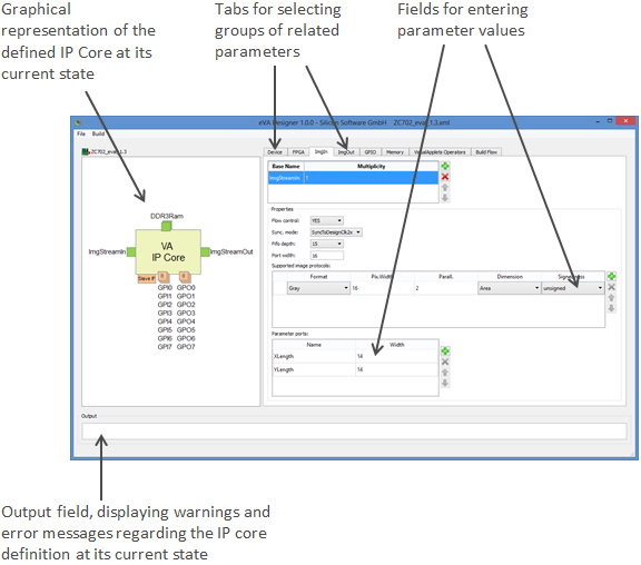
The GUI of supports you as it reacts to any of your inputs.
The graphical representation of the defined IP Core (in the left hand panel of the program window) displays all interfaces you have defined at a given moment. The graphical representation reacts to any input (adding or deleting interfaces) immediately.
-
All interfaces using FIFOs are displayed in green.
-
Multiple interfaces of the same kind are displayed accordingly:
-
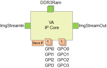
Up to three interfaces of the same kind are displayed as a pile of the exact number of interfaces. Example: 2 memory interfaces:

-
More than three interfaces of the same kind are displayed as a pile of three with a figure informing about the actual number of interfaces. Example: 4 GPI and 4 GPO interfaces:

-
The output field immediately informs you if your IP core definition is not congruent with other entries you make into . e.g., if the interfaces you defined don’t match the VisualApplets operators you defined for connecting to these interfaces within the IP core.
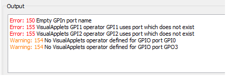
The output field reacts to any input (like adding or deleting interfaces or operators) immediately.
To create a new IP core definition, i.e., to define the interfaces of the programmable IP core you want to integrate into your FPGA design:
-
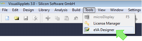
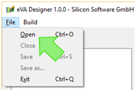
Start .
-
From the menu, select .
The start window of opens:
-
From the menu, select .
-
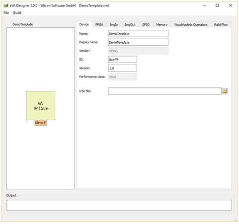
Select an XML template (or an HW description file you have been working on earlier) from your file system to be loaded into .
The XML template is now loaded into :
![[Note]](../common/images/admon/note.png) |
Continuing Work on a Hardware Description File |
|---|---|
|
You can of course also re-open individual hardware description files you have already been working on, or one of the fully filled-in example files. In this case, the graphical representation of the IP core shows the interfaces that have already been specified:
|
-
Go to the tab.
-
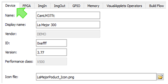
Enter first information regarding the hardware that contains the FPGA you want to equip with image processing applications:
-
Name:Enter the name of your target hardware product.
-
Display Name: Define an alias name for your hardware that you want to display in the VisualApplets GUI. Space characters are allowed.
-
Vendor (display field): Name of your company (i.e., the product’s vendor). The value of that string is preset by Basler and cannot be changed. The vendor name will be visible in the VisualApplets graphical user interface. (The example HW description files show DEMO in this place.)
-
ID: Enter a four-digit hexadecimal identification number of your hardware platform which can be read out via the runtime system. You are free to enter any value here. The value is intended for hardware identification by the VisualApplets user. Example: 0xabcd
-
Version: Enter the version of your hardware product. You are free to enter any value here. The value is intended for HW version identification by the VisualApplets user.
-
Performance Class: Here, the performance class of the XML template you selected is displayed. For details regarding the available performance classes, see section Performance Classes.
-
Icon File (optionally): You can enter here the path to a small graphics file that will display later in VisualApplets together with the name of your hardware platform.
-
-
Go to the tab.
-
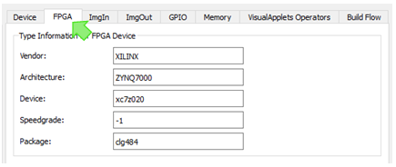
Enter information regarding the FPGA you want to integrate an IP core in under :
FPGA Vendor name (e.g., XILINX).
FPGA series and FPGA model of your FPGA, e.g., ZYNQ7000.
Device name (FPGA type) of your FPGA (without speed grade and package details), e.g., xc7z020.
Speed grade of your FPGA, e.g., -1
Package identification of your FPGA, e.g., clg484
-
Under , specify the properties of iDesignClk:
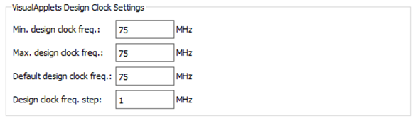
Minimum frequency of the Visual Applets Core design.
Maximum frequency of the Visual Applets Core design.
Default frequency of the Visual Applets Core design.
Step size by which the frequency of the Visual Applets Core may be adapted.
If you specify a frequency here (instead of entering the same value in all three upper fields), you allow the VisualApplets user to set the design clock for a specific design to a value within your value range. See 'Clock Interface' for general information on the clock system.
Surrounding FPGA Design Needs to Support the Defined Frequency Make sure your surrounding FPGA design provides the frequency you define here for the IP Core design. If you allow the VisualApplets user to adapt the design clock (by specifying a frequency here instead of entering the same value in all three fields), you need to make sure that
-
your surrounding FPGA design has the flexibility to adapt its input to iDesignClk, and
-
your FPGA design is able to provide all frequencies within the specified value range.
-
-
Under , enter which FPGA resources you maximally allow an image processing application (in the VA IP Core) to use:
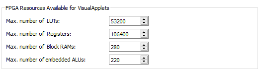
Maximum number of FPGA LUTs which may be used by the Visual Applets design.
Maximum number of FPGA registers which may be used by the Visual Applets design.
Maximum number of block rams of the FPGA which may be used by the Visual Applets design.
Maximum number of embedded ALUs of the FPGA which may be used by the Visual Applets design.
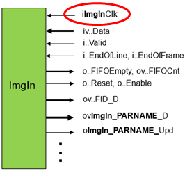
The image streaming ports ImgIn are general purpose image communication interfaces for writing image data from surrounding FPGA logic into the VA IP Core. The ImgIn ports consist of a simple FIFO interface plus additional parameter ports. The interface ports are thoroughly parameterized. In addition to the existing parameters, you can define additional registers for forwarding parameters to the connected FPGA logic.
Image data enters the VA IP Core by interface ports of type ImgIn. Multiple classes of ImgIn ports may be defined and for each of them multiple instances are possible.
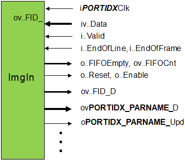
The following table describes the interface signals where PORTID is the name of the corresponding image input port class and X is a port number for differentiating several ports of the same class:
|
ポート |
Direction |
Width |
説明 |
|---|---|---|---|
|
iPORTIDXClk |
In |
1 |
Clock for writing to FIFO. This input is ignored when the port is configured for synchronous communication. ImgIn Interface configuration is described 'Defining ImgIn Interface Classes'. |
|
ivPORTIDXData |
In |
PORTIDWidth |
Write data (interpreted as pixel data, or as and-of-line or and-of-frame flag) |
|
iPORTIDXValid |
In |
1 |
Perform write access |
|
iPORTIDXEndOfLine |
In |
1 |
Signal current write access as end-of-line notification. Write data is then not interpreted as pixel data. |
|
iPORTIDXEndOfFrame |
In |
1 |
Signals end of frame. If this flag is activated data doesn’t contain pixel values. The end-of-frame signal must coincide with the end-of-line signal. |
|
oPORTIDXFIFOFull |
Out |
1 |
Input FIFO is full, no further data is accepted. |
|
ovPORTIDXFIFOCnt |
Out |
Ceil Log2(PORTIDFIFODepth). Ceil Log2 is the number of bits required for representing the value. |
Number of words in input FIFO. This signal can be used to generate FIFO flags like Almost Full. |
|
oPORTIDXReset |
Out |
1 |
Reset signal of the process |
|
oPORTIDXEnable |
Out |
1 |
Enable signal of the process |
|
ovPORTIDX_PARNAME_D |
Out |
S |
Data of the parameter PARNAME. S depends on the selected bit width. This signal is generated for each parameter defined. |
|
oPORTIDX_PARNAME_Upd |
Out |
1 |
This signal is set to ‘1’ for one clock cycle when the parameter PARNAME is updated from the runtime software. This signal is generated for each parameter defined. |
|
ovPORTIDX_FID_D |
Out |
Ceil Log2(N). Ceil Log2 (N) is the number of bits required for representing the value (N-1). |
Predefined parameter which notifies about the current image data format. N is the number of image formats specified for this port. |
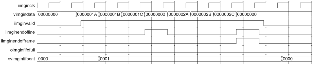
The following figure shows the timing of image communication through an ImgIn interface for a simple example where a frame with two lines of three 32-bit gray pixel values is transferred. In the waveform the name part PORTIDX has been substituted by imgin.
Various different protocols can be driven through a single ImgIn port. VisualApplets supports the following image formats:
-
grayXxP: gray image with X bits per pixel and parallelism P
-
rgbYxP: color image with Y/3 bits per color component (red, green, blue) and parallelism P
-
hsiYxP: color image with Y/3 bits per color component (HSI color model) and parallelism P
-
hslYxP: color image with Y/3 bits per color component (HSL color model) and parallelism P
-
hsvYxP: color image with Y/3 bits per color component (HSV color model) and parallelism P
-
yuvYxP: color image with Y/3 bits per color component (YUV color model) and parallelism P
-
ycrcbYxP: color image with Y/3 bits per color component (YCrCb color model) and parallelism P
-
labYxP: color image with Y/3 bits per color component (LAB color model) and parallelism P
-
xyzYxP: color image with Y/3 bits per color component (XYZ color model) and parallelism P
You can define an ImgIn interface class to support any combination of these formats, provided the platform design which is surrounding the VA IP Core supports the appropriate configuration of image communication channels.
You can specify if pixel components are being interpreted as signed or unsigned.
You can define various classes of ImgIn interfaces. Those interface classes may differ in number and kind of supported image protocols, supported data width, used clock signals, and in many other aspects. Each ImgIn interface class can be available more than one time on the VA IP Core.
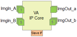
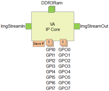
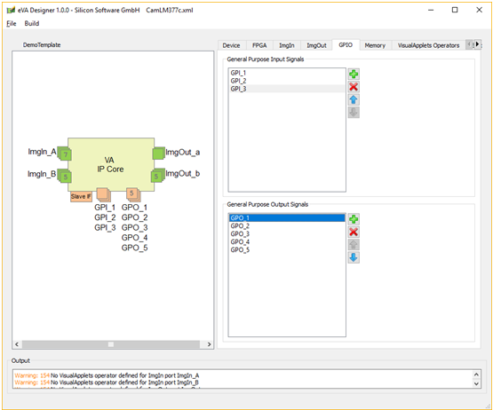
The example IP Core in the figure above shows two ImgIn classes and two ImgOut classes. Multiple instances of both classes are available: This VA IP Core provides 7 ImgIn ports of ImgIn class ImgIn_A, 5 ImgIn ports of ImgIn class ImgIn_B, 2 ImgOut ports of ImgOut class ImgOut_a, and 5 ImgOut ports of ImgOut class ImgOut_b.
|
Related Operators in VisualApplets |
|---|---|
|
For each defined ImgIn class, one or more platform-specific VisualApplets ImgIn operators may be generated later (see 'Defining Hardware-Specific Operators' for details). Those operators can (after IP core integration) be instantiated within VisualApplets and then implement the interface. If more than one interface port of the same configuration (class) exists, the instances of the corresponding operator can connect to any of them controlled by the resource management of VisualApplets. Resource management of VisualApplets: In VisualApplets, for each ImgIn class a resource with the same name is set up. In this resources dialog of VisualApplets, the allocation can be defined. |
To define the ports that allow image streaming into the eVA IP Core:
-
Go to the tab.
-
Click the plus
 icon.
icon.
-
Into field , enter the name of the ImgIn interface class you want to define. Double-click into the field to write.
-
In field , define how many ImgIn interfaces of this class you want to have on your VA IP Core. Double-click into the field to write.
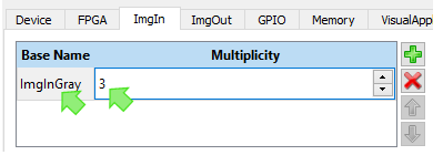
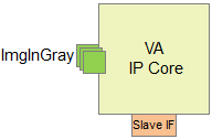
The defined ImgIn ports (in our example, 3 interfaces of class ImgInGray) are immediately visible in the graphical representation of the IP Core:
-
Define further properties of the ImgIn interface class:
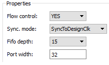
This parameter decides if the VisualApplets application is allowed to temporarily stop the incoming image data flow or not. If set to YES, the internal flow control mechanism for pausing input data will be implemented. If set to NO, the flow control mechanism will not be implemented. Implementation of the flow control mechanism is sensible if you have a stoppable image source connected to the ImgIn port. If you use a non-stoppable source, select NO.
-
: flow control mechanism for pausing input data is implemented.
-
: no flow control mechanism for pausing input data is implemented.
This parameter signals the relation of the image interface clock (iPORTIDXClk on the ImgIn port) and the design clock (iDesignClk on the IP Core). Following values are possible:
-
SyncToDesignClk – interface ports are synchronous to iDesignClk. The external clock input of the image interface port is ignored.
-
SyncToDesignClk2x – interface ports are synchronous to iDesignClk2x. The external clock input of the ImgIn port is ignored.
Double Pixel Depth Available If you use iDesignClk2x for the ImgIn port, you may define an image protocol with twice the bit depth you define for port iv..Data (i.e., the product of bit width and parallelism can be double-size). In this case, an automatic parallel-up with factor 2 is carried out by the system.
-
– asynchronous interface: The interface ports are synchronized to the external clock input of the ImgIn interface.
If you select , you need to
-
provide a clock signal at the iImgInClk port of the ImgIn interface, and to
-
define clock domain transition constraints in the synthesis constraints (constraints file).
Double Pixel Depth Available If you provide a clock signal frequency at the iImgInClk port that is much higher than iDesignClk, you may define an image protocol with twice the bit depth you define for port iv..Data (i.e., the product of bit width and parallelism can be double-size). In this case, an automatic parallel-up with factor 2 is carried out by the system.
Use iDesignClk or iDesignClk2x Basler recommends to use iDesignClk or iDesignClk2x for synchronization whenever possible.
Define here the depth of the buffer FIFO for input data which at least needs to be implemented by an attached VisualApplets interface operator. The value must be a power of two minus 1 between 15 and 1023.
Define here the width of the image data port.
-
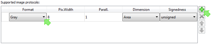
You need to define the image protocols you want this ImgIn interface class to support. Define one protocol after the other until all protocols you want to specify are there.
|
Related Operators in VisualApplets |
|---|---|
|
After integration of the VA IP Core into your FPGA design, the developer of the image processing application instantiates an ImgIn operator in VisualApplets and defines which of the protocols supported by the ImgIn interface (and the operator itself) is implemented by this operator instance in a given application. |
-
Click on the arrow in column and select the format of your choice from the format list:
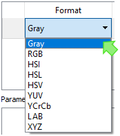
Find more detailed description on the supported image formats in 'Supported ImageIn Formats'.
-
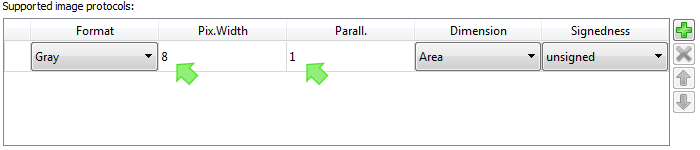
Double-click on the field in column .
Enter the required pixel data bit width (value range: [1..64]).
The pixel data width is limited to 64 bit. The pixel data width for all non-gray color formats must be a multiple of 3 and is limited to 63 bit.
-
Double-click on the field in column . Enter the required parallelism.
The parallelism P defines the number of pixels which are contained in a single data word at the interface port. It must be chosen from the following set of allowed values: P = {1, 2, 4, 8, 16, 32, 64}. Packing of image data into words of a given interface width N (Port width, see above) must follow certain rules:
-
The data of all P pixels must fit in a single word of length N. The data is stored LSB aligned which means that for a pixel width Z (Z=X for grey, Z=Y for color) data is distributed as follows: Pixel[0]->Bits[0..Z-1] .. Pixel[P-1]->Bits[(P-1)*Z..P*Z-1].
-
For RGB images the three color components are packed LSB aligned into a sub word [0..Y-1] in the following order: red uses the bits [0..Y/3-1 ], green the bits [Y/3..2*Y/3-1] and blue the bits [2*Y/3..3*Y/3-1].
-
For HSI color images the same rules than for RGB applies where H takes the role of red, S that of green and I the role of blue.
-
For HSL color images the same rules than for RGB applies where H takes the role of red, S that of green and L the role of blue.
-
For HSV color images the same rules than for RGB applies where H takes the role of red, S that of green and V the role of blue.
-
For YUV color images the same rules than for RGB applies where Y takes the role of red, U that of green and V the role of blue.
-
For YCrCb color images the same rules than for RGB applies where Y takes the role of red, Cr that of green and Cb the role of blue.
-
For LAB color images the same rules than for RGB applies where L takes the role of red, A that of green and B the role of blue.
-
For XYZ color images the same rules than for RGB applies where X takes the role of red, Y that of green and Z the role of blue.
-
-
Click on the arrow in column to select the image dimension of the protocol you are defining.
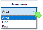
The meaning of the dimension is as follows:
-
(default): The image is structured by end-of-line and end-of-frame markers. In VisualApplets, image dimension is named 2D. An area camera could be an 2D image source.
-
: The image is structured by end-of-line markers. There are no end-of-frame markers which divide the incoming lines into frames. In VisualApplets, image dimension is named 1D. A line camera could be an 1D image source.
-
: There are no end-of-line and no end-of-frame markers which divide the incoming image data into lines and frames. The image-in stream consists of an endless pixel stream with a width of 1 pixel. In VisualApplets, image dimension is named 0D.
-
-
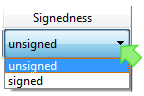
Click on the arrow in column and select the image dimension of the protocol you are defining.
-
Unsigned (default): Pixel data are interpreted as unsigned pixel components.
-
Signed: Pixel data are interpreted as signed pixel components
-
-
Repeat steps 1 - 5 until you have defined all image protocols you want the image class to support.
|
Internal ID for Image Protocol Definitions |
|---|---|
|
Implicitly it is assumed that the kernel size is 1x1. Each listed protocol is numbered, the list starts from zero. These numbers form the protocol IDs for a given ImgIn class. The ID is not displayed on the GUI. Thus, each ImgIn class you define has an internal ID list of the image protocols you define. In one of the next steps, you can define one or more VisualApplets ImgIn operators the instances of which can connect to the defined ImgIn class (details how to define operators you find in 'Defining Hardware-Specific Operators'). To each of these operators you can assign all or a subset of the image protocols you specified for the concerning image port. In VisualApplets, the ImgIn operator will provide a parameter where the VisualApplets user can select an image format from a list of options. According to the selection, the corresponding ID will be assigned to the related IP core ImgIn port (ov..FID_D). This enables the attached glue logic to adapt its behavior according to the selected format. |
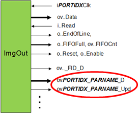
You can define additional parameters you want your ImgIn interface class to have. These (dynamic) parameters can be set during runtime. They can be accessed via the runtime interface (see 'Runtime Software Interface').
These parameters are communicated via the register slave interface (see 'Register Slave Interface') of the VA IP Core.
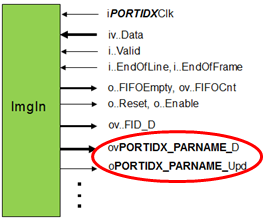
ovPORTIDX_PARNAME_D: Data of the parameter PARNAME. Direction: Out. You can define the bit width. This signal is generated for each parameter defined.
oPORTIDX_PARNAME_Upd: Direction: Out. Bit width: 1. This signal is set to ‘1’ for one clock cycle when the parameter PARNAME is updated from the runtime software. This signal is generated for each parameter defined.
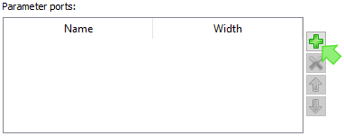
To define additional parameters for the ImgIn interface class:
-
Go to the area of the program window.
-
Click the plus
icon.
-
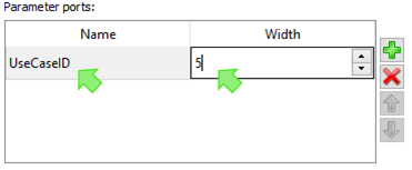
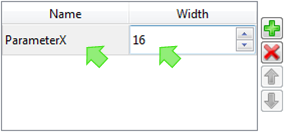
Into field , enter the name of the parameter you want to define. Double-click into the field to write.
-
In field , define the width of the parameter port {1,64}. Double-click into the field to write.
Mapping between Slave Interface Data Width and Actual Register Width Registers which are accessed through the register interface may have any width between 1 and 64. Mapping between the slave interface data width and the actual register width of a VisualApplets parameter is done automatically. When the width of a register is bigger than the width of the register interface the runtime software will divide the access automatically. A single parameter then consumes more than one register address.
-
Repeat steps 2 – 4 until you have defined all parameters you want the image class to support.
After carrying out all steps described in 'Setting up ImgIn Ports', 'Defining Image Protocols for an ImgIn Interface Class', and 'Defining Additional Parameters for an ImgIn Interface Class', you have set up your first ImgIn interface class.
-
If you need more ImgIn interface classes, define the next ImgIn Interface class by re-starting with 'Setting up ImgOut Ports' again.
|
Define as Many ImgIn Interface Classes as You Need |
|---|---|
|
You can define as many interface classes as you need. For setting up the next ImgIn interface class, start with the steps described in section 'Setting up ImgIn Ports' again. |
The image streaming ports ImgOut are general purpose image communication interfaces for writing image data from the VA IP Core into the surrounding FPGA logic. The ImgOut ports consist of a simple FIFO interface plus additional parameter ports. The interface ports are thoroughly parameterized. In addition to the existing parameters, you can define additional registers for forwarding parameters to the connected FPGA logic.
Image data leaves the VA IP Core by interface ports of type ImgOut. Multiple classes of ImgOut ports may be defined and for each of them multiple instances are possible.
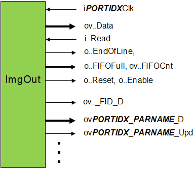
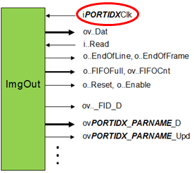
The following table describes the interface signals where PORTID is the name of the corresponding image input port class and X is a port number for differentiating several ports of the same class:
|
ポート |
Direction |
Width |
説明 |
|---|---|---|---|
| iPORTIDXClk | In | 1 | Clock for reading from FIFO. This input is ignored when the port is configured for synchronous communication. (ImgOut interface configuration is described in 'Defining ImgOut Interface Classes'.) |
| ivPORTIDXData | Out | PORTIDWidth | Data for custom read |
| iPORTIDXRead | In | 1 |
Perform read access |
| iPORTIDXEndOfLine | Out | 1 | Signals end of line. If this flag is activated data doesn’t contain pixel values. |
| iPORTIDXEndOfFrame | Out | 1 | Signals end of frame. If this flag is activated data doesn’t contain pixel values. The end-of-frame signal must coincide with the end-of-line signal. |
| oPORTIDXFIFOEmpty | Out | 1 | Output FIFO is empty |
| ovPORTIDXFIFOCnt | Out |
Ceil Log2( PORTIDFIFODepth ) |
Number of words in output FIFO. This signal can be used to generate FIFO flags like “Almost Empty”. |
| oPORTIDXReset | Out | 1 | Reset signal of the process |
| oPORTIDXEnable | Out | 1 | Enable signal of the process |
| ovPORTIDX_PARNAME_D | Out | S | Data of the parameter PARNAME. S depends on the selected bit width. This signal is generated for each parameter defined. |
| oPORTIDX_PARNAME_Upd | Out | 1 | This signal is set to ‘1’ for one clock cycle when the parameter PARNAME is updated from the runtime software. This signal is generated for each parameter defined. |
| ovPORTIDX_FID_D | Out | Ceil Log2(N). Ceil Log2 (N) is the number of bits required for representing the value (N-1). | Predefined parameter which notifies about the current image data format. N is the number of image protocols specified for this port. |
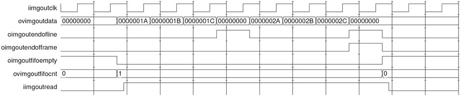
The following figure shows the timing of image communication through an ImgOut interface for a simple example: A frame with two lines of three 32-bit gray pixel values is transferred. In the waveform the name part PORTIDX has been substituted by imgout.
Various different protocols can be driven through a single ImgOut port. VisualApplets supports the following image formats:
-
grayXxP: gray image with X bits per pixel and parallelism P
-
rgbYxP: color image with Y/3 bits per color component (red, green, blue) and parallelism P
-
hsiYxP: color image with Y/3 bits per color component (HSI color model) and parallelism P
-
hslYxP: color image with Y/3 bits per color component (HSL color model) and parallelism P
-
hsvYxP: color image with Y/3 bits per color component (HSV color model) and parallelism P
-
yuvYxP: color image with Y/3 bits per color component (YUV color model) and parallelism P
-
ycrcbYxP: color image with Y/3 bits per color component (YCrCb color model) and parallelism P
-
labYxP: color image with Y/3 bits per color component (LAB color model) and parallelism P
-
xyzYxP: color image with Y/3 bits per color component (XYZ color model) and parallelism P
You can define an ImgOut interface class to support any combination of these formats, provided the platform design which is surrounding the VA IP Core supports the appropriate configuration of image communication channels.
You can define various classes of ImgOut interfaces. Those interface classes may differ in number and kind of supported image protocols, supported data width, used clock signals, and in many other aspects. Each ImgOut interface class can be available more than one time on the VA IP Core.
The example in the figure above shows two ImgIn classes and two ImgOut classes. Multiple instances of both classes are available: This VA IP Core provides 7 ImgIn ports of ImgIn class ImgIn_A, 5 ImgIn ports of ImgIn class ImgIn_B, 2 ImgOut ports of ImgOut class ImgOut_a, and 5 ImgOut ports of ImgOut class ImgOut_b.
|
Related Operators in VisualApplets |
|---|---|
|
For each defined ImgOut class, you can later define one or more platform-specific VisualApplets ImgOut operators (see 'Defining Hardware-Specific Operators' for details). Those operators can (after IP core integration) be instantiated within VisualApplets and then implement the interface. If more than one interface port of the same configuration (class) exists, the instances of the corresponding operator can connect to any of them controlled by the resource management of VisualApplets. |
To define the ports that allow image streaming from the VA IP Core to the surrounding FPGA design:
-
Go to the tab.
-
Click the plus
icon.
-
Into field , enter the name of the ImgOut interface class you want to define. Double-click into the field to write.
-
In field , define how many ImgOut interfaces of this class you want to have on your VA IP Core. Double-click into the field to write.
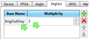
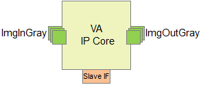
The defined ImgOut ports (in our example, 3 interfaces of class ImgOutGray) are immediately visible in the graphical representation of the IP Core:
-
Define further properties of the ImgOut interface class:
-
If you select Yes, a flow control mechanism for pausing output data is implemented. Value Yes allows VisualApplets designs to block reading from the output FIFO for any duration. A FIFO-full signal signals that no further data may be written.
-
If you select No, no flow control mechanism for blocking output data is implemented.
This parameter signals the relation of the image interface clock (iPORTIDXClk on the ImgOut port) and the design clock (iDesignClk on the IP Core). Following values are possible:
-
SyncToDesignClk – interface ports are synchronous to iDesignClk. The external clock input on the ImgOut port is ignored.
-
SyncToDesignClk2x – interface ports are synchronous to iDesignClk2x. The external clock input on the ImgOut port is ignored.
Double Pixel Depth Available If you use iDesignClk2x for the ImgOut port, you may define an image protocol with twice the bit depth you define for port ov..Data (i.e., the product of bit width and parallelism can be double-size). In this case, an automatic parallel-up with factor 2 is carried out by the system.
-
– asynchronous interface: The interface ports are synchronized to the external clock input of the ImgOut interface.
If you select , you need to
-
provide a clock signal at the port of the ImgOut interface, and to
-
define clock domain transition constraints in the synthesis constraints (constraints file).
Double Pixel Depth Available If you use iDesignClk2x for the ImgOut port, you may define an image protocol with twice the bit depth you define for port ov..Data (i.e., the product of bit width and parallelism can be double-size). In this case, an automatic parallel-up with factor 2 is carried out by the system.
Use iDesignClk or iDesignClk2x Basler recommends to use iDesignClk or iDesignClk2x for synchronization whenever possible.
Define here depth of the buffer FIFO for output data which at least needs to be implemented by an attached Visual Applets interface operator. The value must be a power of two minus 1 between 15 and 1023.
Define here the width of the image data port.
-
You need to define the image protocols you want this ImgOut interface class to support. You define one protocol after the other until all protocols you want to specify are there.
|
Related Operators in VisualApplets |
|---|---|
|
After integration of the VA IP Core into your FPGA design, the developer of the image processing application instantiates an ImgOut operator in VisualApplets and defines which of the protocols supported by the ImgOut interface (and the operator itself) is implemented by this operator instance in a given application. |
-
Click on the arrow in column and select the format of your choice from the format list:
A more detailed description of the supported image formats you find in 'Supported ImageOut Formats'.
-
Double-click on the field in column .
Enter the required pixel data bit width (value range: [1..64]).
The pixel data width is limited to 64 bit. The pixel data width for all non-gray color formats must be a multiple of 3 and is limited to 63 bit.
-
Double-click on the field in column . Enter the required parallelism.
The parallelism P defines the number of pixels which are contained in a single data word at the interface port. It must be chosen from the following set of allowed values: P = {1, 2, 4, 8, 16, 32, 64}. Packing of image data into words of a given interface width N (Port width, see above) must follow certain rules:
-
The data of all P pixels must fit in a single word of length N. The data is stored LSB aligned which means that for a pixel width Z (Z=X for grey, Z=Y for color) data is distributed as follows: Pixel[0]->Bits[0..Z-1] .. Pixel[P-1]->Bits[(P-1)*Z..P*Z-1].
-
For RGB images the three color components are packed LSB aligned into a sub word [0..Y-1] in the following order: red uses the bits [0..Y/3-1 ], green the bits [Y/3..2*Y/3-1] and blue the bits [2*Y/3..3*Y/3-1].
-
For HSI color images the same rules than for RGB applies where H takes the role of red, S that of green and I the role of blue.
-
For HSL color images the same rules than for RGB applies where H takes the role of red, S that of green and L the role of blue.
-
For HSV color images the same rules than for RGB applies where H takes the role of red, S that of green and V the role of blue.
-
For YUV color images the same rules than for RGB applies where Y takes the role of red, U that of green and V the role of blue.
-
For YCrCb color images the same rules than for RGB applies where Y takes the role of red, Cr that of green and Cb the role of blue.
-
For LAB color images the same rules than for RGB applies where L takes the role of red, A that of green and B the role of blue.
-
For XYZ color images the same rules than for RGB applies where X takes the role of red, Y that of green and Z the role of blue.
-
-
Click on the arrow in column to select the image dimension of the protocol you are defining.
The meaning of the dimension is as follows:
-
(default): The image is structured by end-of-line and end-of-frame markers. In VisualApplets, image dimension is named “2D”.
-
: The image is structured by end-of-line markers. There are no end-of-frame markers which divide the incoming lines into frames. In VisualApplets, image dimension is named “1D”.
-
: There are no end-of-line and no end-of-frame markers which divide the incoming image data into lines and frames. The image-in stream consists of an endless pixel stream with a width of 1 pixel. In VisualApplets, image dimension is named “0D”. A line camera could be an 0-D image source.
-
-
Click on the arrow in column and select the image dimension of the protocol you are defining.
-
Unsigned (default): Pixel data are packed as unsigned pixel components.
-
Signed: Pixel data are packed as signed pixel components
-
-
Repeat steps 1 - 5 until you have defined all image protocols you want the image class to support.
|
Internal ID for Image Protocol Definitions |
|---|---|
|
Implicitly it is assumed that the kernel size is 1x1. Each listed protocol is numbered, the list starts from zero. These numbers form the protocol IDs for a given ImgOut class. The ID is not displayed on the GUI. Thus, each ImgOut class you define has an internal ID list of the image protocols you define. In one of the next steps, you can define VisualApplets ImgOut operators. The instances of these operators can connect to the defined ImgOut class (details how to define operators you find in 'Defining Hardware-Specific Operators'). To each ImgOut operator you can assign all or a subset of the image protocols you specified for the concerning image port. In VisualApplets, the ImgOut operator will provide a parameter where the VisualApplets user can select an image format from of a list of options. According to the selection, the corresponding ID will be assigned to the related IP core ImgOut interface port (ov..FID_D). This enables the attached glue logic to adapt its behavior according to the selected format. |
You can define additional parameters you want your ImgOut interface class to have. These (dynamic) parameters can be set and re-set during runtime. They can be accessed via the runtime interface (see 'Runtime Software Interface').
During runtime they are communicated via the register slave interface (see 'Register Slave Interface') of the VA IP Core.
ovPORTIDX_PARNAME_D: Data of the parameter PARNAME. Direction: Out. You can define the bit width as described below. This signal is generated for each parameter defined.
oPORTIDX_PARNAME_Upd: Direction: Out. Bit width: 1. This signal is set to ‘1’ for one clock cycle when the parameter PARNAME is updated from the runtime software. This signal is generated for each parameter defined.
To define additional parameters for the ImgOut interface class:
-
Go to the area of the program window.
-
Click the plus
icon.
-
Into field , enter the name of the parameter you want to define. Double-click into the field to write.
-
In field , define the width of the parameter port {1,64}. Double-click into the field to write.
Mapping between Slave Interface Data Width and Actual Register Width Registers which are accessed through the register interface may have any width between 1 and 64. Mapping between the slave interface data width and the actual register width of a VisualApplets parameter is done automatically. When the width of a register is bigger than the width of the register interface the runtime software will divide the access automatically. A single parameter then consumes more than one register address.
-
Repeat steps 2 – 4 until you have defined all parameters you want the image class to support.
After carrying out all steps described in 'Setting up ImgOut Ports', 'Defining Image Protocols for an ImgOut Interface Class', and 'Defining Additional Parameters for an ImgOut Interface Class', you have set up your first ImgOut interface class.
-
If you need more ImgOut interface classes, define the next ImgOut interface class by re-starting with 'Setting up ImgOut Ports' again.
|
Define as Many ImgOut Interface Classes as You Need |
|---|---|
|
You can define as many interface classes as you need. For setting up the next ImgOut interface class, start with the steps described in 'Setting up ImgOut Ports' again. |
General purpose signals IN (GPIs) and General purpose signals OUT (GPOs) may enter or leave the VA IP Core. These signals can be used for triggering and process control.
The number of GPI and GPO signals you can configure as described below.
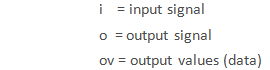
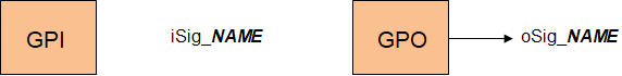
Any GPI or GPO signal which has been defined in the eVA platform description has a corresponding input or output port in the VA IP Core. The signal ports will get the following names when NAME is the name of the GPI or GPO signal as it will show up in VisualApplets:
-
iSig_NAME for an input signal of width 1
-
oSig_NAME for an output signal of width 1
All dedicated I/O signals are synchronous to the clock iDesignClk.
| ポート | Direction | Width | 説明 |
|---|---|---|---|
| iSig_NAME | In | 1 | Input signal on GPI port |
| oSig_NAME | Out | 1 | Output signal on GPO port |
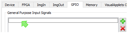
To define the GPI ports of the VA IP Core:
-
Go to the tab.
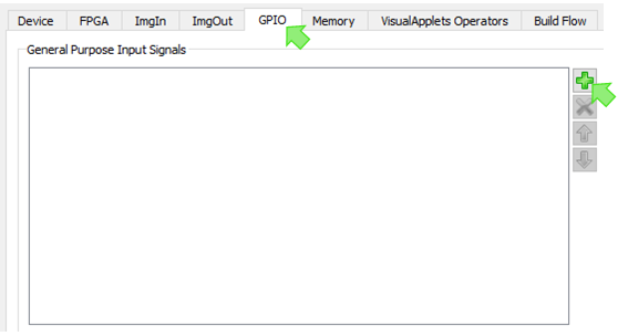
-
ペインの area, click the plus
icon.
-
Into the field that is available now, enter the name of the GPI port you want to define. Double-click into the field to write.
-
Repeat steps 3 and 4 until you have defined all GPI ports you want to have available on your VA IP Core.
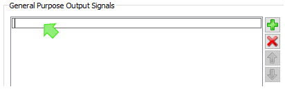
-
Go to the area.
-
Click the plus
icon.
-
Into the field that is available now, enter the name of the GPO port you want to define. Double-click into the field to write.
-
Repeat steps 7 and 8 until you have defined all GPO ports you want to have available on your VA IP Core.
The defined GPI and GPO ports are immediately visible in the graphical representation of the IP Core:
|
Related Operators in VisualApplets |
|---|---|
|
For the GPI and GPO signals, you can later define one or more platform-specific VisualApplets GPIO operators (see 'Defining Hardware-Specific Operators' for details). These operators are made up by connectors to one or several of the GPIO resources. These operators can (after IP core integration) be instantiated within VisualApplets and then implement access to one or more GPI and/or GPO ports of the IP Core. The VisualApplets environment checks for resource conflicts (the same input/output pin cannot be used by two operator instances). |
You can connect the VA IP Core to external memory via an abstracted memory interface. You can connect any kind of memory via a single interface mechanism. You simply need to adapt the eVA memory interface protocol via glue logic to the memory controller you use.
You can configure how many memory interface ports will be available on the VA IP Core. For each port, you can define the interface properties individually (i.e., address and data width).
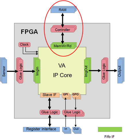
When image buffer operators shall be used VisualApplets need access to external memory. In most cases this will be a number of RAM banks. The memory interface ports are not visible within the VisualApplets design entry. But operators which use external memory (like ImageBuffer) consume an abstract resource called RAM handled by the resource management of VisualApplets.
The eVA memory interface has been designed in a way that allows to connect a variety of different memory architectures via a single interface mechanism. The abstracted interface is basically a slave interface where the external memory controller masters the access. The slave is demanding write or read accesses via independent FIFO interfaces for writing and reading commands. The attached master needs to acknowledge fetching a command and can perform the access at any time. A flag interface enables the slave to notice when a demanded access has been performed. There are optional signals for additional information, like the number of commands which are waiting to be fetched. Those signals may help the memory controller master to optimize memory access.
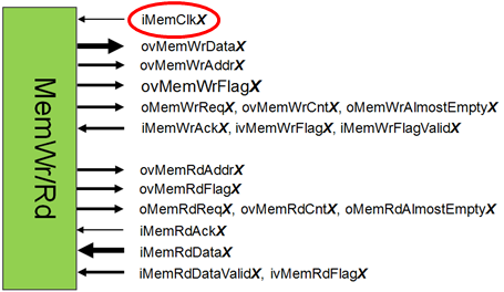
The eVA framework is able to operate with multiple memory ports. The I/O ports of the resulting VA IP Core get a suffix X where X is the number of the memory interface channel.
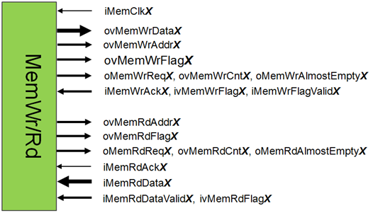
-
All I/O is synchronous to the externally supplied clock iMemClkX when an asynchronous interface is specified. Alternatively, the synchronization mode can be SyncToDesignClk where all I/O is synchronous to iDesignClk, or SyncToDesignClk2x with I/O synchronous to iDesignClk2x.
|
iDesignClk2x Recommended |
|---|---|
|
Basler recommends to use the iDesignClk2x clock signal on memory ports. |
-
Write and read requests can occur concurrently; write and read data paths to memory are completely separated.
-
Write accesses are demanded using the ports ovMemWrDataX, ovMemWrAddrX, ovMemWrFlagX, and oMemWrReqX which in the following shall be called a write command.
-
Read accesses are demanded using the ports ovMemRdAddrX, ovMemRdFlagX, oMemRdReqX which in the following shall be called a read command.
-
The controller acknowledges when an access command has been fetched. After an acknowledge (iMemWrAckX for write, iMemRdAckX for read), in the next clock tick the next command may be provided. The command is signalled by the according request ports (oMemWrReqX for write, oMemRdReqX for read).
-
Some VA operators require that accesses are tagged by a flag (ovMemWrFlagX, ovMemRdFlagX). After the access has been performed, the controller must return this flag to the memory interface (ivMemWrFlagX, ivMemRdFlagX). There is a minimal width of the tags which must be provided:
-
MemWrFlagWidth >= 4 -
MemRdFlagWidth >= 8
-
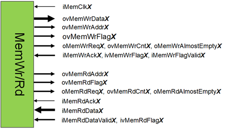
The following table provides a detailed description of the memory interface ports where X is a port number for differentiating several memory ports:
|
ポート |
Direction |
Width |
説明 |
|---|---|---|---|
|
iMemClkX |
In |
1 |
Memory interface clock. This input is ignored when the port is configured for synchronous communication. |
|
ovMemWrDataX |
Out |
MemDataWidthX |
Write data output to memory controller |
|
ovMemWrAddrX |
Out |
MemAddrWidthX |
Write address |
|
ovMemWrFlagX |
Out |
MemWrFlagWidthX |
Write flag output |
|
oMemWrReqX |
Out |
1 |
Write Request |
|
iMemWrAckX |
In |
1 |
Acknowledge that write data is taken by the memory controller |
|
oMemWrAlmostEmptyX |
Out |
1 |
Only single write command available |
|
ovMemWrCntX |
Out |
MemWrCntWidthX |
Number of available write commands |
|
ivMemWrFlagX |
In |
MemWrFlagWidthX |
Write flag output from the controller |
|
iMemWrFlagValidX |
In |
1 |
Write flag input valid – signals that iMemWrFlagX is valid, which means that write access which had been marked with corresponding oMemWrFlagX has been executed. |
|
ovMemRdAddrX |
Out |
MemAddrWidthX |
Read address output |
|
ovMemRdFlagX |
Out |
MemRdFlagWidthX |
Read flag output |
|
oMemRdReqX |
Out |
1 |
Read Request |
|
iMemRdAckX |
In |
1 |
Acknowledge that read address has been taken by the memory controller |
|
oMemRdAlmostEmptyX |
Out |
1 |
Only single read address available |
|
ovMemRdCntX |
Out |
MemRdCntWidthX |
Number of available read addresses |
|
ivMemRdFlagX |
In |
MemRdFlagWidthX |
Read flag input – only valid when iMemRdDataValidX is asserted |
|
ivMemRdDataX |
In |
MemDataWidthX |
Read data input |
|
iMemRdDataValidX |
In |
1 |
Read data valid |
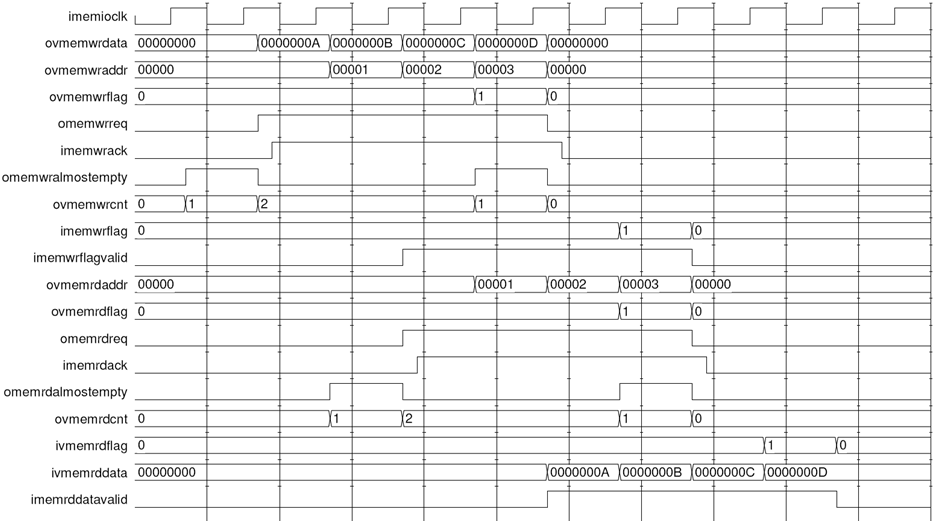
The following figure illustrates the interface protocol for a write and read access where both accesses overlap. For simplicity, a memory controller with a fixed read latency of two clock cycles has been assumed:
You can define various classes of memory interfaces. Those interface classes may differ in supported data width, address, used clock signals, and in many other aspects. Each memory interface class can be available more than one time on the VA IP Core.
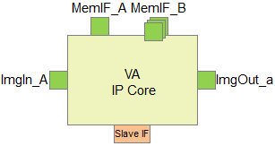
The example VA IP Core (in the figure above) shows two memory interface classes. Multiple instances of both classes are available: This VA IP Core provides 1 memory interface of interface class MemIF_A and 3 memory interfaces of interface class MemIF_B.
To define the memory interfaces of your VA IP Core:
-
Go to the tab.
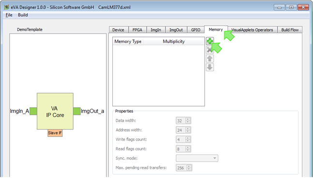
-
Click the plus
icon.
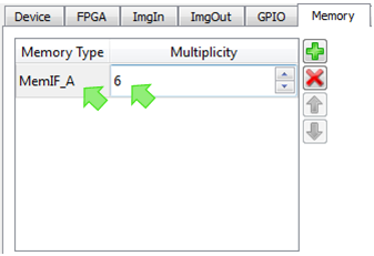
-
Into field , enter the name of the memory interface class you want to define. Double-click into the field to write.
-
In field , define how many memory interfaces of this class you want to have on your VA IP Core. Double-click into the field to write.
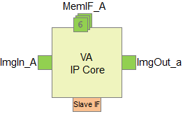
The defined memory interfaces (in our example, 6 interfaces of class MemIF_A) are immediately visible in the graphical representation of the IP Core:
-
Define further properties of the memory interface class:
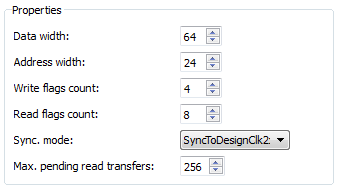
Enter the data width for the memory interface class.
Enter here the address width.
Enter here the width of ovMemWrFlagX (minimum width: 4)
Enter here the width of ovMemRdFlagX (minimum width: 8)
Some VisualApplets operators require that accesses are tagged by a flag (ovMemWrFlagX, ovMemRdFlagX). After the access has been performed, the controller must return this flag to the memory interface (ivMemWrFlagX, ivMemRdFlagX). There is a minimal width of the tags which must be provided: MemWrFlagWidth >= 4, MemRdFlagWidth >= 8
This parameter signals the relation of the memory interface clock (iMemClkX on the memory interface) and the design clock (iDesignClk on the IP Core). Following values are possible:
-
SyncToDesignClk – interface ports work synchronous to iDesignClk. The external clock input to the interface clock port is ignored.
-
SyncToDesignClk2x – interface ports are synchronous to iDesignClk2x. The external clock input to the interface clock port is ignored.
iDesignClk2x Recommended Basler recommends to use the iDesignClk2x clock signal on memory ports.
-
Async – asynchronous interface: The interface ports are synchronized to the external clock input to clock port iMemClkX.
If you select Async, you need to
-
provide a clock signal at the iMemClkX port of the memory interface, and to
-
define the clock domain switch in the synthesis constraints (constraints file).
-
Enter here the maximum number of data words in the read pipeline outside the core. This value is relevant for calculating the minimum buffer depth for incoming read data.
-
-
Repeat steps 2 – 5 to define all memory interface classes you need.
VisualApplets offers an amount of operator libraries for defining image processing applications. All libraries – except one – are hardware independent, i.e., the contained operators can be used in any design for any target hardware.
The only exception are operators which connect directly to the hardware that surrounds the VA IP Core: The ImgIn interfaces, the ImgOut interfaces, and the memory interfaces. These are hardware-specific operators, and they have to be designed together with the IP Core itself.
To define the ImgIn operators for your target hardware:
-
Go to the tab.
-
Go to the tab.
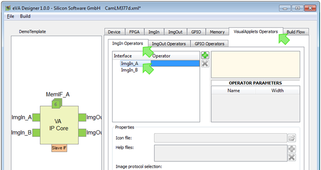
Under tab , you find a list of the ImgIn interface classes you have defined earlier.
(In our example, these are ImgIn_A and ImgIn_B.)
-
Click on the ImgIn interface class for which you want to define connecting ImgIn operators.
-
Click the plus
icon.
Now, the options for defining operators for this ImgIn interface class are displayed:
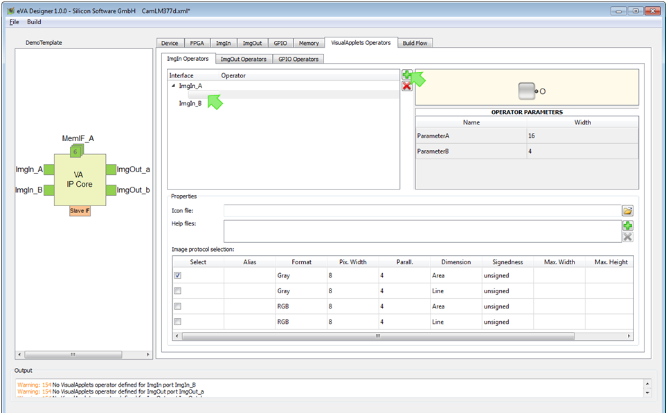
-
Into field , enter the name of the operator you want to define. Double-click into the field to write.
-
In field , define path to an icon file that will be displayed in VisualApplets on the graphical representation of the operator. How the complete graphical representation will look like in VisualAplets you can see in the right upper panel of the program window:
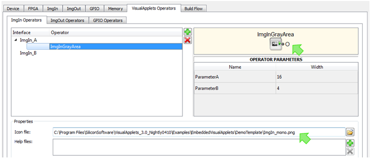
-
In field , define path to an HTML help file that describes the operator and its parameters. Click the plus icon to select a file from your file system. The name of the start
*.htmlfile must be named<nameofOperator>.htmland be placed in the first place. Other files may be images, CSS files, etc.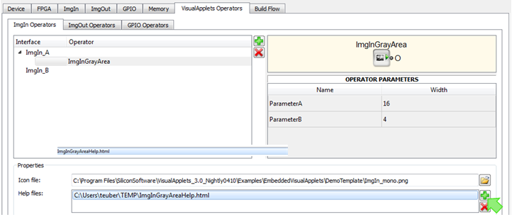
-
Repeat step 7 if you want to add more than one file containing information on this operator. You can load a batch of files (i.e., a HTML file system with graphics files) in one step. The first HTML file you list here will be regarded as the main help file (starting point for help file system).
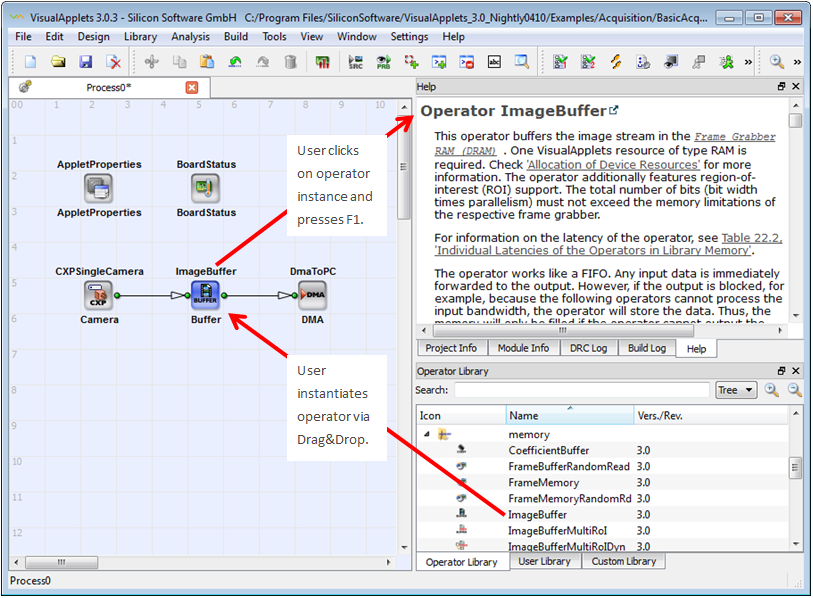
The main help file will be visible in the VisualApplets help panel as soon as a user instantiates an operator, clicks on the operator instance in the design window and presses F1:
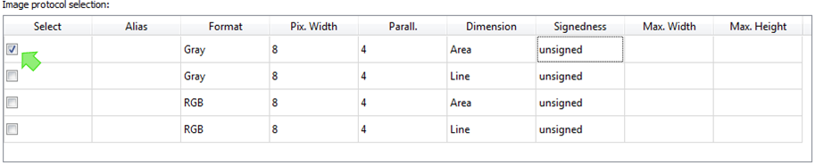
Panel displays the image protocols attached to the selected interface class:
-
Select here the image protocol(s) you want this operator to support.
-
If you want to, define maximal image width and maximal image height for a selected image protocol in the two last columns.
-
Repeat steps 4 – 10 to define additional operators being connectible to the selected interface class.
-
Repeat steps 3 – 10 to define operators for the other interface classes.
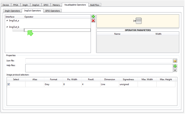
To define the ImgOut operators for your target hardware:
-
Go to the tab.
-
Go to the tab.
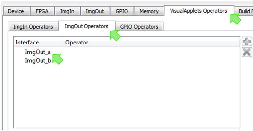
Under tab , you find a list of the ImgOut interface classes you have defined earlier. (In our example, these are ImgOut_a and ImgOut_b.)
-
Click on the ImgOut interface class for which you want to define connecting ImgOut operators.
-
Click the plus
icon.
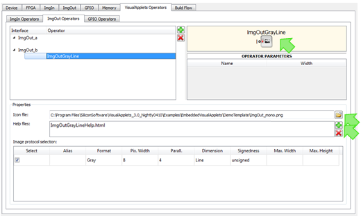
Now, the options for defining operators for this ImgOut interface class are displayed:
-
Into field , enter the name of the operator you want to define. Double-click into the field to write.
-
In field , define the path to an icon file that will be displayed in VisualApplets on the graphical representation of the operator. How the complete graphical representation will look like in VisualAplets you can see in the right upper panel of the programm window:
-
In field , define path to an HTML help file that describes the operator and its parameters. Click the plus icon to select a file from your file system.
-
Repeat step 7 if you want to add more than one file containing information on this operator. You can load a batch of files (i.e., a HTML file system with graphics files) in one step. The first HTML file you list here will be regarded as the main help file (starting point for help file system).
The main help file will be visible in the VisualApplets help panel as soon as a user instantiates an operator, clicks on the operator instance in the design window, and presses F1.
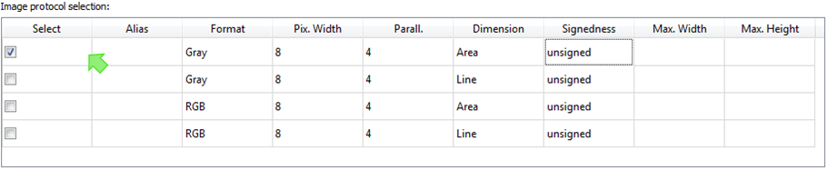
Panel displays the image protocols attached to the selected interface class:
-
Select here the image protocol(s) you want this operator to support.
-
If you want to, define maximal image width and maximal image height for a selected image protocol in the two last columns.
-
Repeat steps 4 – 10 to define additional operators being connectible to the selected interface class.
-
Repeat steps 3 – 10 to define operators for the other interface classes.
You can define GPIO operators that provide an configurable number of GPI and GPO ports. When designing image processing applications, the user can connect these ports to the actual GPI and GPO ports of the eVA IP Core.
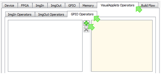
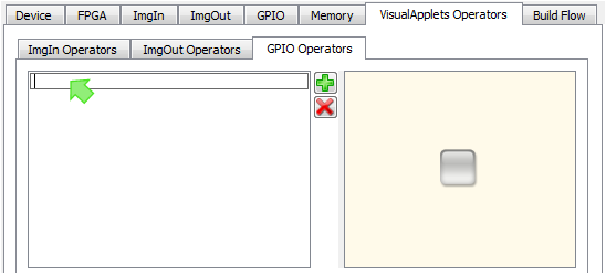
To define GPIO operators for your target hardware:
-
Go to the tab.
-
Go to the tab.
-
Click the plus
icon.
-
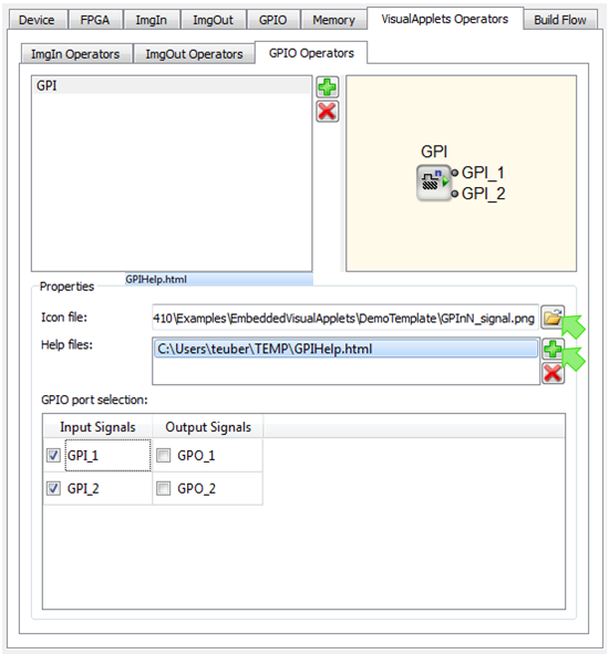
Into the field that opens, enter the name of the operator you want to define. Double-click into the field to write.
-
In field , define path to an icon file that will be displayed in VisualApplets on the graphical representation of the operator. How the complete graphical representation will look like in VisualAplets you can see in the right upper panel of the programm window.
-
In field , define path to an HTML help file that describes the operator and its parameters. Click the plus icon to select a file from your file system.
-
Repeat step 6 if you want to add more than one file containing information on this operator. You can load a batch of files (i.e., a HTML file system with graphics files) in one step. The first HTML file you list here will be regarded as the main help file (starting point for help file system).
The main help file will be visible in the VisualApplets help panel as soon as a user instantiates an operator, clicks on the operator instance in the design window, and presses F1.
Panel displays the GPI and GPO interfaces you defined for the eVA IP Core:
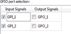
-
Select here the GPI and GPO ports of the IP core you want this operator to be able to connect to.
-
Repeat steps 3 – 8 to define additional operators being connectible to GPI and GPO ports of the IP core.
After you defined the IP Core black box as described in sections 'Common Interfaces for all Platforms' to 'Defining Hardware-Specific Operators', you can build the IP Core black box (VHDL). In 'Embedding and Simulating the IP core', you will integrate this black box into you your FPGA design.
Together with the IP Core black box, automatically generates a simulation environment for the individual interfaces you defined, and an according test bench. Section 'Embedding and Simulating the IP core' describes in detail how you can use them.
For generating the IP core black box, you do not need to specify any build flow details. Also the hardware-specific operators you may define at a later stage.
To generate the IP Core black box:
-
Enter all information regarding your target hardware and the required IP Core interfaces as described in sections 'Common Interfaces for all Platforms' to 'Defining Hardware-Specific Operators'.
-
Open the XML or
*.evafile containing your hardware and core interface description. -
From menu , select
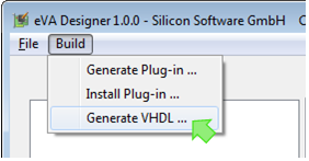
-
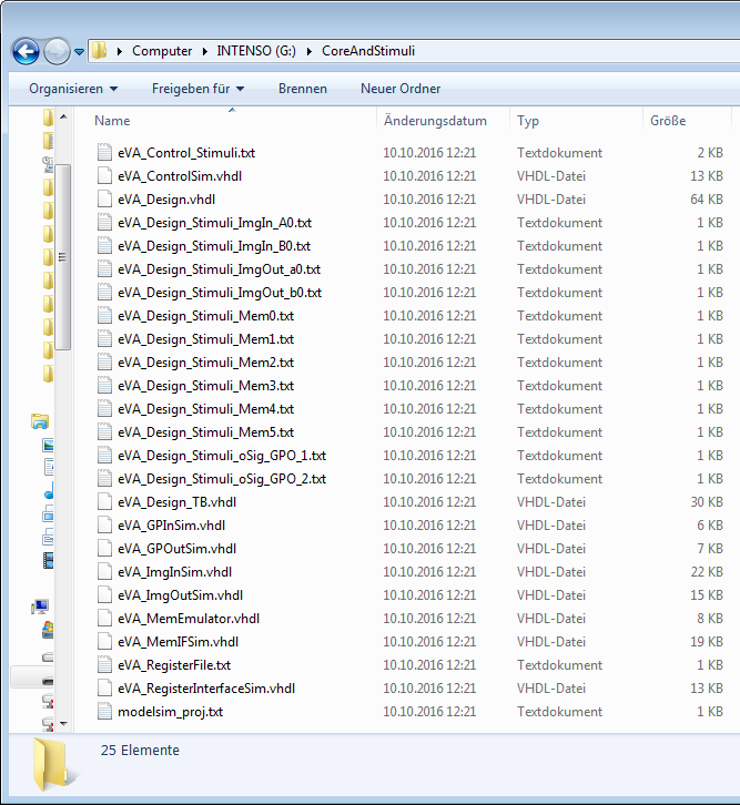
Create a dedicated directory where you will to store the generated files.
-
Click on . Now, all related files are generated automatically. You find them in the selected directory:
-
Follow the instructions in section 'Embedding and Simulating the IP core'. You will learn about
-
integrating the IP core black box (that you’ve just created) into your FPGA design (VHDL),
-
using the stimuli and simulation files that support you during VHDL integration.
-
