In the previous sections, the data flow model, the layout and the rules of links of VisualApplets projects were explained. This chapter will outline the parametrization of modules and links in your design.
Application behavior and bandwidth do not only depend on the operators you use in your design, but also quite strongly on the parametrization of the modules and links. Module properties define the behavior of each module, while link properties describe the protocol between the modules. Module and link properties directly depend on each other and mutually influence their availability or ranges.
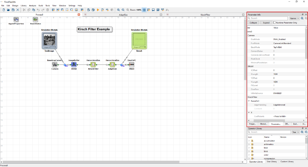
You can change module properties either in the Module Properties dialog or in the Parameter Info view. The Parameter Info view displays all parameters of all operators in the active design and thus provides a good overview of all configured parameters. The Module Properties dialog provides more details about the parameters. You can edit parameters in both views, however, adding metadata is only possible in the Module Properties dialog.
The Parameter Info is located in the Information Panel in the top right side of the VisualApplets main window.
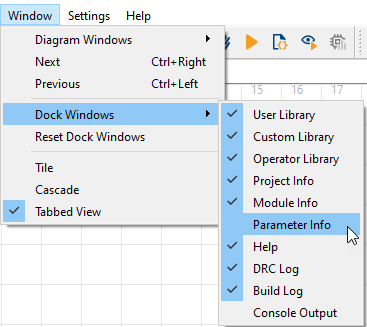
If the Parameter Info doesn't open up at start, you
can open it via the menu bar by selecting → → .
The Parameter Info view shows all parameters and their operators of the active design. You can also edit the parameters in the Parameter Info view.
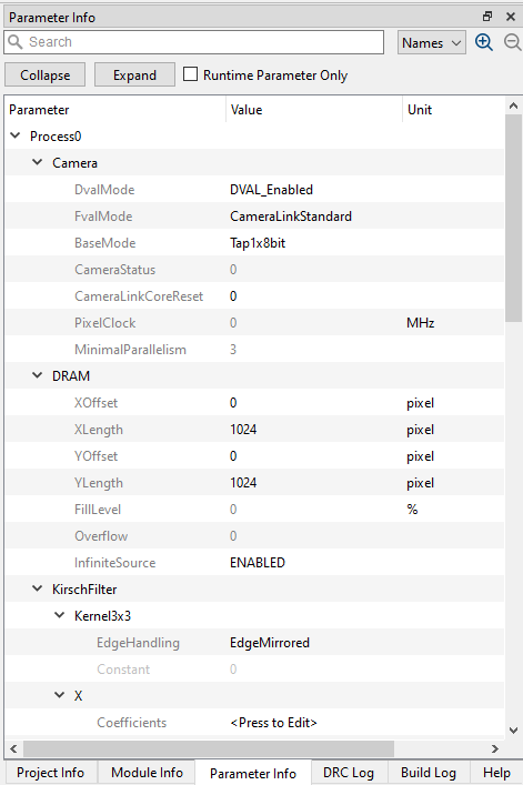
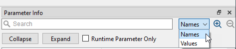
The Parameter Info view provides a search function that allows you to search for parameters, parameter values, or operator names. You can use the Runtime Parameter Only filter to display only dynamical parameters, i.e. parameters that you can edit during runtime.
-
To access the Module Properties dialog, double-click a module, or right-click on a module and select .
The Module Properties dialog lists all required settings a module. Note that for each module a different set of parameters is available (depending on the operator that has been instantiated for creating the module).
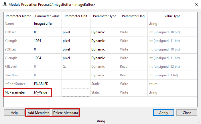
The following figure shows the parameters of an ImageBuffer operator in the Module Properties dialog:
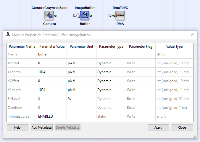
The Module Properties window lists all available parameters of a module. In this context, each parameter represents a module property. The parameters are displayed with entries in the following columns:
-
Parameter Name:
The name of the parameter.
When adding a parameter to a module (see below), you can enter a name for the new parameter here.
-
Parameter Value
The actual value of an parameter.
You can edit this field to change a value.
-
Parameter Unit
The unit of a parameter. Can be pixel, seconds, lines, etc.
-
Parameter Type
Here, you can set a parameter to static or dynamic. Static parameters cannot be changed after the build process of an applet, while dynamic parameters can be changed when the applet is already in use on the frame grabber hardware. Mostly, static parameters will require less FPGA resources than dynamic parameters.
-
Parameter Flag
The flag of a parameter indicates whether a parameter is
-
read only (Read), or has
-
read & write access (Write).
-
-
Value Type
The type of the parameter value. There are four different types of parameter values:
-
String
Any string, e.g., file names.
-
Values
Values of different types (unsigned, signed, double) and ranges.
-
列挙
A list of enumeration values such as Disabled or Enabled.
-
Field Parameters
A field parameter consists of an array, a list, or a matrix of values. It is mostly used for kernel coefficients, lookup tables and other lists. Value ranges and size of list can be dynamic. Note that the displayed bit width is not equal to the actual parameter range. Moreover, a parameter is always unsigned, even if it is declared as a signed value in the column.
-
![[Note]](../common/images/admon/note.png) |
Differences Between Modules |
|---|---|
|
How many parameters and which parameters are available for a certain module is different from module to module (depending on the underlying operator). Nevertheless, each module will possess at least one parameter called Name. |
![[Warning]](../common/images/admon/warning.png) |
No Undo option |
|---|---|
|
It is not possible to cancel a change. All changes are immediately applied. |
To edit a parameter:
-
Click on a parameter value and type in the new value.
Some value types have special editing options:
String: A string parameter you can edit by simply typing in the new string. Some string parameters are file name parameters. In this case, a file selection dialog will open.
Values: For editing a value, use the spin box next to the parameter value to increase or decrease the value. The step size of the parameter defines the minimal increase/decrease.
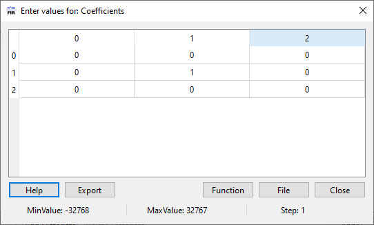
Fields: With field parameters, a new window will open for editing which shows all field elements of the parameter. The following figure shows the fields of a FIRoperatorNxM operator:
There are three different ways you can edit the field parameter values of a module:
-
You can simply edit each field element individually.
-
Alternatively, you can use a list from file to fill the field parameter values.
-
You can import the file by clicking on the button.
-
You can also export the current field parameter setting to file by clicking the button.
File Format of Import File -
The import file has to contain a list of ASCII values.
-
Each value has to be stated in a separate line.
-
The lines have to be separated by carriage return (CR) and line feed (LF).
-
The file has to be in text only format ([NameOfFile].txt).
If the file contains more values than there are in the field, the first values of the file are used (as many as are required to fill the field). The following values in the file have no effect.
If the file contains less values than there are in the field, all values of the file are used exactly one time. The last positions of the field (for which there are no values in the file) will remain unchanged.
-
-
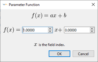
A third possibility to edit the elements of a filed is the Parameter function dialog.
-
Click on to open the function dialog (see next figure).
Using this dialog, a linear function can be used to edit the elements. A linear function consists of the elements a = slope, b = offset, and x = index of field element. In the dialog, a and b can be edited.
-
Enter values for a and b.
The first element of a filed has index 0. For matrix elements, the elements are consecutively numbered row by row.
-
-
![[Important]](../common/images/admon/important.png)
After a parameter has been edited, it has to be applied.
-
Click on in the Module properties window to apply the settings.
A new parameter value is discarded if it is not within the allowed parameter value range.
|
Click before closing the window |
|---|---|
|
It is recommended to click on Apply before closing the parameter. This way, you will see warnings if the value you entered is not accepted. |
-
Close the Module properties window by clicking on .
Most operators of the Parameters library provide an autocompletion and syntax highlighting functionality for specific parameters. Autocompletion is available for the following parameters in the following operators:
| Operators | パラメーター | Activation |
|---|---|---|
| EnumParamTranslator |
WriteAction, ReadAction |
Typing “${” |
|
DisplayHierarchy |
TAB key |
|
| FloatParamTranslator |
WriteAction, ReadAction |
Typing “${” |
|
DisplayHierarchy |
TAB key |
|
| IntParamTranslator |
WriteAction, ReadAction |
Typing “${” |
|
DisplayHierarchy |
TAB key |
|
| LinkParamTranslator |
WriteAction |
Typing “${” |
| EnumParamReference |
Reference |
TAB key |
|
DisplayHierarchy |
TAB key |
|
| FloatFieldParamReference |
Reference |
TAB key |
|
DisplayHierarchy |
TAB key |
|
| FloatParamReference |
Reference |
TAB key |
|
DisplayHierarchy |
TAB key |
|
| IntFieldParamReference |
Reference |
TAB key |
|
DisplayHierarchy |
TAB key |
|
| IntParamReference |
Reference |
TAB key |
|
DisplayHierarchy |
TAB key |
|
| ResourceReference |
Reference |
TAB key |
|
DisplayHierarchy |
TAB key |
|
| StringParamReference |
Reference |
TAB key |
|
DisplayHierarchy |
TAB key |
|
| IntParamSelector |
Reference |
TAB key |
|
DisplayHierarchy |
TAB key |
|
| FloatParamSelector |
Reference |
TAB key |
|
DisplayHierarchy |
TAB key |
|
| EnumVariable |
DisplayHierarchy |
TAB key |
| FloatVariable |
DisplayHierarchy |
TAB key |
| IntVariable |
DisplayHierarchy |
TAB key |
Table 5. Availability of Autocompletion and Syntax Highlighting
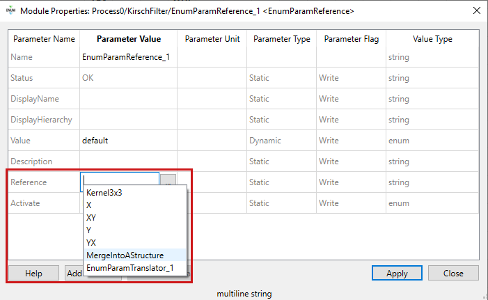
To use the autocompletion for a reference operator, click into the Parameter Value field of the Reference or DisplaHierarchy parameter, and press the TAB key. VisualApplets then offers you a selection of valid values in a drop-down list box.
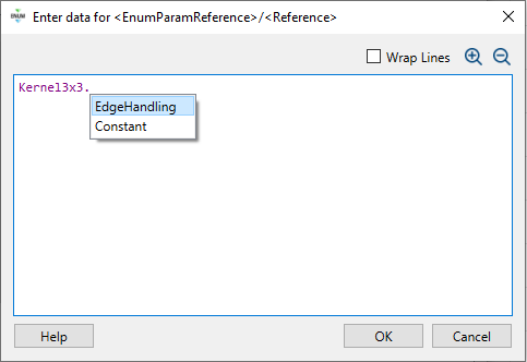
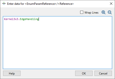
If you click the three dots  next to the Parameter Value field, the
Enter data for <operator>/<parameter> dialog opens
up. In this dialog, you see the data with syntax highlighting and can further use
the autocompletion feature:
next to the Parameter Value field, the
Enter data for <operator>/<parameter> dialog opens
up. In this dialog, you see the data with syntax highlighting and can further use
the autocompletion feature:
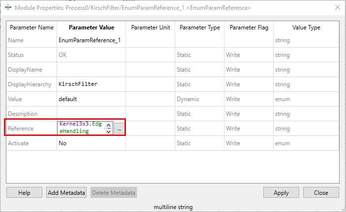
Syntax highlighting also works in the Module Properties:
To use the autocompletion functionality in the WriteAction and ReadAction parameters of translate operators, type “${” into the Parameter Value field:
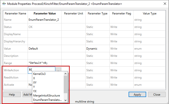
Syntax highlighting also works for the WriteAction and ReadAction parameters of translator operators.
To use autocompletion for the DisplayHierarchy parameter of translate operators, click into the Parameter Value field of the DisplaHierarchy parameter, and press the TAB key.
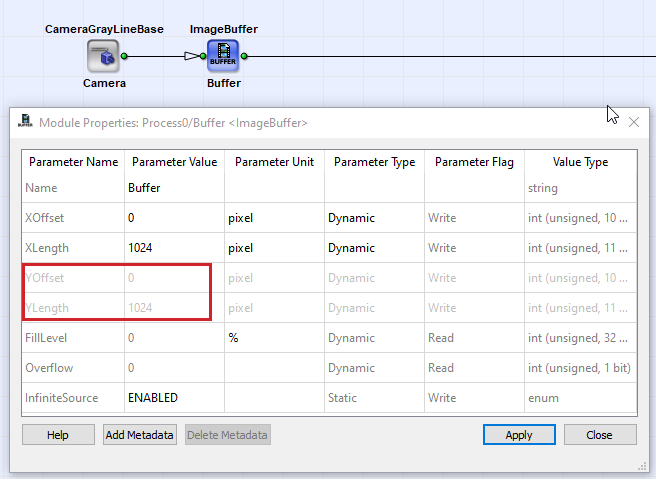
The allowed value range of a parameter might change when link properties or by the setting of other properties. If this happens, the old parameter value might be in an illegal state. In this case, the parameter is marked red, to indicate, that the current setting will not pass the design rule check. You have to correct the parameter value until it is in the valid range.
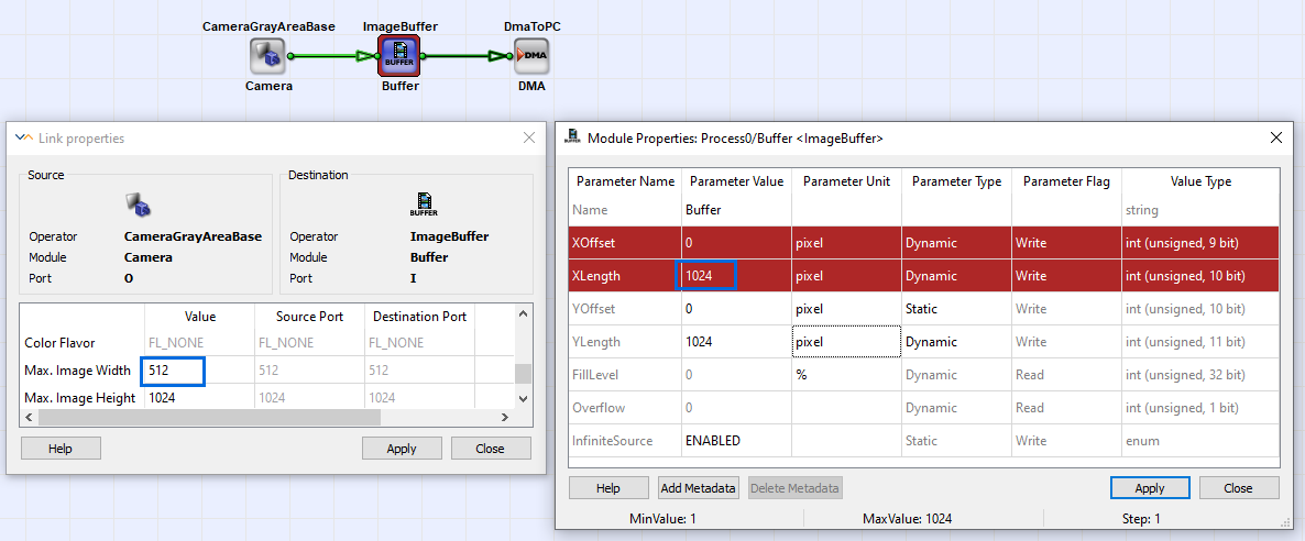
The previous figure showed an example of parameters in an illegal state. In this case, the parameter value is not within the allowed range, as the XLength + XOffset is greater than the parametrized maximum image width of the input link.
For each module, metadata parameters can be added. Metadata parameters are string parameters. To add a metadata parameter click on the button in the module properties window. A new parameter is now added to the parameter list. By clicking the name and the value, both can be edited. Metadata parameters are read / write parameters. To delete a metadata parameter, simply select the parameter and click on .
Metadata parameters are often used for versioning and commenting.
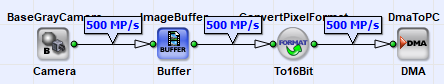
Each link between modules is defined by its link properties. You access link properties via double click on a link or via right click and selection Properties.
Each link has the following link properties:
-
Bit Width
Defines the bit width of the link for one pixel. Thus if color links are used, the bit width represents all color planes. For image protocol VALT_SIGNAL the bit width is always one bit.
-
Arithmetic
The arithmetic of a link. Can be signed or unsigned. If set to signed, a two's complement signed arithmetic is used. The sign bit is included in the bits specified with property bit width. For image protocol VALT_SIGNAL the arithmetic is always set to unsigned.
-
Parallelism
Specifies the number of pixel which are transferred in parallel between two modules within one design clock cycle. For image protocol VALT_SIGNAL the parallelism is always set to one. More information about the parallelism can be found in 'Bandwidth of an Applet'.
-
Kernel Columns
Defines the number of kernel columns. For image protocol VALT_SIGNAL the number of kernel columns is always set to one.
-
Kernel Rows
Defines the number of kernel rows. For image protocol VALT_SIGNAL the number of kernel rows is always set to one.
-
Image Protocol
The image protocol defines which protocol to transfer data is used by the link. The following protocols are available:
-
VALT_IMAGE2D: Two-dimensional images, e.g., area scan cameras.
-
VALT_LINE1D: One-dimensional images, i.e., images with an unlimited image height, e.g., line scan cameras.
-
VALT_PIXEL0D: A simple stream of pixels with no image dimension information.
-
VALT_SIGNAL: One bit signals which are valid at every clock cycle. Used for signal processing such as trigger systems.
More information on image protocols is presented in 'Image Protocols, Image Dimensions and Data Structure'.
-
-
Color Format
The color format can either be VAF_GRAY, VAF_COLOR or VAF_NONE. For image protocol VALT_SIGNAL the color format is always set to FL_GRAY.
-
Color Flavor
Defines the flavor of the color format. For image protocol VALT_SIGNAL the color flavor is always set to FL_GRAY.
-
Max. Image Width
Defines the maximum image width of a link. Images transported on the link must not exceed this value but may be less than the value. The Max. Image Width has no influence on links with Image Protocol VALT_PIXEL0D and VALT_SIGNAL. For these image protocols the Max. Image Width is ignored. More information can be found in 'Data Flow ' and in 'Image Protocols, Image Dimensions and Data Structure'.
-
Max. Image Height
Defines the maximum image height of a link. Images transported on the link must not exceed this value but may be less than the value. The Max. Image Height has no influence on links with Image Protocol VALT_LINE1D, VALT_PIXEL0D and VALT_SIGNAL. For these image protocols the Max. Image Height is ignored. More information can be found in 'Data Flow ' and in 'Image Protocols, Image Dimensions and Data Structure'.
![[Tip]](../common/images/admon/tip.png) |
Visualization on GUI |
|---|---|
|
For visualization of the according link properties, VisualApplets provides two GUI buttons in the toolbar of the program window:
Display Link Info
Display Link Throughput
|


Each module defines the ranges of the link properties at its output itself. Some properties cannot be modified, some properties can only be modified in a specified range while others can arbitrarily be modified. A detailed explanation of the allowed output link formats is given in the respective operator reference in Operator Reference.
To edit a parameter, simply click on a parameter in the "Value" column of the link properties window.
The link properties dialog consists of three columns:
-
値
This is your editing column. Edit your link property values in this column by clicking on the values. If the edited value is not within the allowed parameter range or step size, the edited value is discarded or cannot be inserted. Confirm the new value by leaving the focus of the field or by pressing the Enter key.
-
Source Port
After a new value has been entered in the Value column and has been confirmed, the source operator checks if the new value is accepted. If the new value is not accepted, the parameter and the link will get a red color to show a link property conflict. Thus, if a link property in column source port is dyed red, the source operator does not allow the settings. The values in this column cannot be modified!
-
Destination Port
A click on or or or pressing Esc will apply the new settings for the link. If the new settings are not accepted by the destination operator input port, the link as well the parameter in column Destination Port will be dyed red to indicate the conflict. The values in this column cannot be modified!
A change of a link property can cause the change of another link property or a module parameter value. Canceling changes is not possible. Each change will immediately be applied.
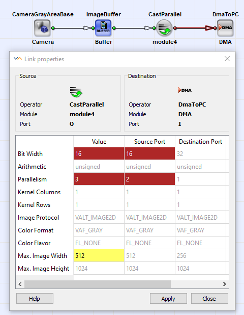
Let's have a look at some examples. The following figure shows a conflict at the source port. The source operator, in this case a CastParallel operator, does not accept a parallelism of three at its output because of the bit width. After the output parallelism has been changed to four, two or one, the conflict is solved.
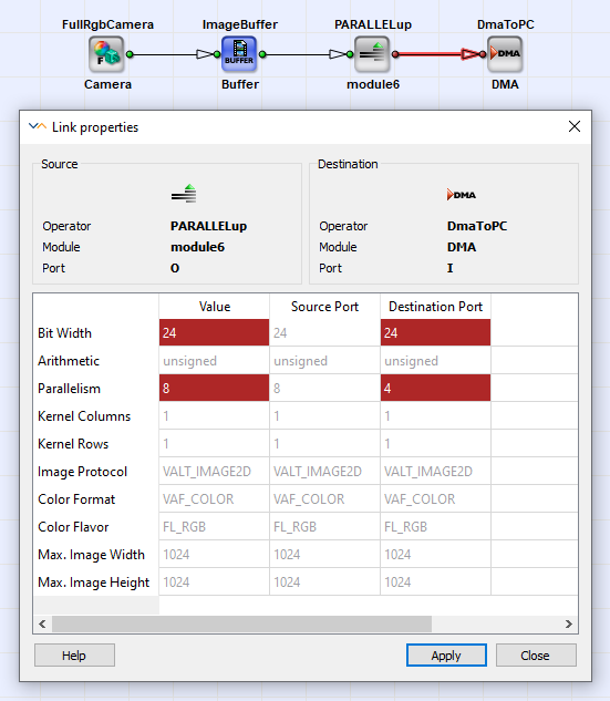
Screenshot Figure 84, 'Invalid Destination Port Link Properties' shows a conflict at the destination port. The destination operator, in this case a DmaToPC operator, does not accept RGB images with this parallelism and bit width. After the parallelism has been reduced to four or five, the conflict is solved.
The link properties are defined by the operator. Some link properties can directly be changed at the operator output links, while others are fixed or are defined by the operator parameters. Moreover, most operators define their link properties in addition from the input link properties. This can result in a link property modification chain through multiple modules. Thus, if a link property has been changed, the parameters and link properties of successive module might change, too.
This propagation chain can result in three results:
-
The modification has been accepted by all successive modules and links. VisualApplets will display all links which have been changed in green, to inform the user about modified link properties.
-
The link modification is not accepted at the link of some module. In this case, check the link for the error. Read the documentation of the source or destination operator to learn about the allowed link formats.
-
The modification causes a conflict with a module parameter. In this case, the module is dyed red as well as the respective module parameter. Check the operator reference for link and parameter dependencies to resolve the conflict.
