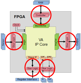
You are ready now to integrate the IP core into your surrounding FPGA design. This basically means implementing and connecting converters between the data communication protocols of the target hardware and the protocols at the IP core interfaces. In particular, you need to care for connecting external interfaces like memory controller, sensor interface and data output.
When you generated the IP core black box (as described in section 'Generating VHDL Code for the IP Core'), not only the IP core black box itself was generated. In the same step, a whole test bench was generated that is already tailored to test the individual interfaces of the IP core while you integrate them into your HDL design.
The test bench enables simulation of data communication through the IP core interfaces during HDL integration. The tools generated for HDL simulation focus on testing the interface protocols and generating stimuli for the circuits attached to the core in the top-level architecture (your HDL design).
In the test bench, each individual interface port which may later be connected via a corresponding VisualApplets operator is simulated independently, driven by file I/O. The simulation entity consists of the following elements:
-
Emulation of slave interface for register access: Configured by file, the simulation module provides a set of registers which can be written and read. There are dedicated registers which connect to the enable and reset signals. You can configure different processes. The actual number of processes of an image processing application is later (after integration) defined in the VisualApplets design. For simulation, you define the number of processes as described in section Emulation of Slave Interface. . Enable and Reset are the only signals which connect to the other simulation modules whose affiliation to a process you can specify through simulation entity parameters (see below). The register interface emulator provides the option to change register values over time according to a stimuli file. In the stimuli file, you can set a value and define when a value should be changed (i.e., set 1, after 10.000 clock cycles set 0).
-
Emulator of image source connected to ImgOut ports. Stimulated by file, this kind of module outputs image data to the ImgOut interface of the IP core. The image protocol ID you can configure according to the image protocols you specified for an image output port.
-
Emulator of frame sink connected to ImgIn ports. This kind of module emulates an operator which is connected to the ImgIn interface of the IP core. The image protocol ID you can configure according to the image protocols you specified for an image input port. The module writes the received data to file.
-
Memory port emulator which acts as if a module is connected which uses RAM. The sequence of write and read accesses is stimulated by a file and read data is output to file.
-
GPIO emulator. Each GPIO signal for output is driven by a signal generator which is configured by a file. Each GPIO signal input is monitored and changes of the signal are written to a report file.
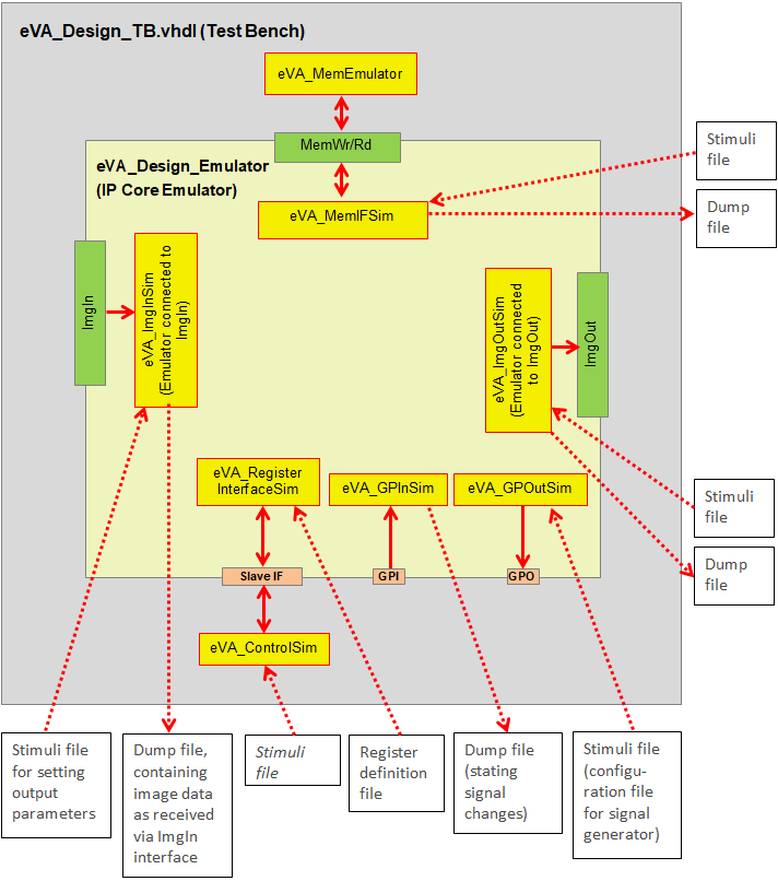
Figure 203. Example Test Bench for IP Core with 1 ImgIn Interface, 1 ImgOut Interface, 1 Memory Interface, 1 GPI, 1 GPO, and Slave Interface
For RTL level simulation, a VHDL file eVA_Design.vhdl has been created. This file contains a package with name eVA_<PLATFORMNAME> ( <PlatformName> is the platform name you defined as described in 'Entering Platform Details'). This package contains two components:
-
eVA_Design: black box for the Visual Applets IP Core
-
eVA_Design_Emulator: emulator of Visual Applets IP Core: The emulator implements the file-based stimuli generation for a simulation test bench.
The following shows the code in file eVA_Design.vhdl which would be generated for a most simple VA IP Core consisting only of the slave interface for register access:
       component eVA_Design
       generic(

              RegIFDataWidth : integer := 32;
              RegIFAddrWidth : integer := 16);

       port(

              iDesignClk: in std_logic := '0';
              iDesignClk2x: in std_logic := '0';

              ivRegWrData: in std_logic_vector(RegIFDataWidth-1 downto 0) := (others=>'0');
              ivRegWrAddr: in std_logic_vector(RegIFAddrWidth-1 downto 0) := (others=>'0');
              iRegWrValid: in std_logic := '0';

              ivRegRdAddr: in std_logic_vector(RegIFAddrWidth-1 downto 0) := (others=>'0');
              iRegRdValid: in std_logic := '0';
              ovRegRdData: out std_logic_vector(RegIFDataWidth-1 downto 0) := (others=>'0');
              oRegRdDataValid: out std_logic := '0'

       );
       end component;

       component eVA_Design_Emulator
       generic(

              RegIFDataWidth : integer := 32;
              RegIFAddrWidth : integer := 16;
              NrOfProcesses: integer := 2;
              RegisterDefinitionFile: string := ""

       );
       port(

              iDesignClk: in std_logic := '0';
              iDesignClk2x: in std_logic := '0';

              ivRegWrData: in std_logic_vector(RegIFDataWidth-1 downto 0) := (others=>'0');
              ivRegWrAddr: in std_logic_vector(RegIFAddrWidth-1 downto 0) := (others=>'0');
              iRegWrValid: in std_logic := '0';

              ivRegRdAddr: in std_logic_vector(RegIFAddrWidth-1 downto 0) := (others=>'0');
              iRegRdValid: in std_logic := '0';
              ovRegRdData: out std_logic_vector(RegIFDataWidth-1 downto 0) := (others=>'0');
              oRegRdDataValid: out std_logic := '0'

       );
       end component;
More detailed information about emulating the individual kinds of IP core interfaces you find in the following subsections.
The eVA design emulator has a parameter NrOfProcesses. This parameter is an integer within the range 1 to 16. The parameter has the effect that a set of predefined registers for resetting and enabling the design are created. Following addresses will be configured:
-
0x00: Global Reset
-
0x01: Global Enable
-
0x02 * (i+1): Process Reset for process i (i < NrOfProcesses).
-
0x02 * (i+1) + 0x01: Process Enable for process i (i < NrOfProcesses).
So when NrOfProcesses = 2 the first 6 addresses of the slave interface address space will be used for controlling reset and enable of the emulated design. Each image port will be affiliated to one pair of reset and enable signals controlled by the above registers. After integration, the VisualApplets user will affiliate an interface to a process, as he instantiates an operator as component of a process and connects this operator instance to an interface.
The emulator for the slave interface for register access is further configured by a text file which is set by the entity parameter RegisterDefinitionFile as provided in the above VHDL code. The parameter is set automatically during black box and test bench generation as described in section Generating VHDL Code for the IP Core.
The following commands may be present in the register definition file:
|
コマンド |
説明 |
|---|---|
|
REM |
Rest of line is comment |
|
DEF |
Define register. This command has the following syntax: DEF <addr> <width> <write_read> <init_value>
with the parameters: <init_value>: hexadecimal initial value <addr>: hexadecimal value of register address <width>: bit width of register <write_read>: 1 for write register, 0 for read register |
|
CON |
Connect write register to read register. This command has the following syntax: CON <wrRegAddr> <rdRegAddr>
with the parameters: <wrRegAddr>: address of write register (hex) <rdRegAddr>: address of read register (hex) |
|
WCK |
Wait for a number of clock cycles. The syntax is as follows: WCK <clock_ticks>
with <clock_ticks> giving the number of clock ticks in hexadecimal format. |
|
SET |
Set value of read register SET <rdRegAddr> <value>
with the parameters: <rdRegAddr>: address of read register (hex) <value>: hexadecimal register value |
After the last parameter of any command, you can add a comment preceded by ‘#’.
The following code is an example register definition file which configures two write and two read registers, where one read register is preset after 16 clock cycles (address 0x7) and the other read register (address 0x6) is driven by the write register with address 0x6:
      REM ************************************************************
      REM Command formats: DEF <addr> <width> <write_read> <init_value>
      REM                  CON <wrRegAddr> <rdRegAddr>
      REM                  WCK <clock_ticks>
      REM                  SET <rdRegAddr> <value>
      REM ************************************************************
      DEF 0006 10 1 00000000 #define write reg with width 0x10 at address 0x6
      CON 0006 0006          #create read reg with addr 0x6 connected to
      REM                     write register with address 0x6
      DEF 0007 20 1 00000000 #define write reg with width 0x20 at address 0x7
      DEF 0007 10 0 00000000 #define read register at address 0x7
      WCK 0010               #wait for 16 clock cycles
      SET 0007 0000000C      #set read register value
The emulation of image communication interfaces of type ImgOut is driven by a stimuli file providing information about the sequence of data output.
For any present ImgOut port, the eVA_Design_Emulator entity has a generic <PORTIDX>_StimuliFileName where <PORTIDX> is the name of the corresponding image output port class followed by the port number. Each line within the given file must follow the syntax
<Command> <Data> <EndOfLine> <EndOfFrame> <DataValid>
where <Command> is a three letter command, <Data> provides an hexadecimal data word, and the three remaining parameters correspond to the image protocol flags.
The following table describes the available commands:
|
コマンド |
説明 |
|---|---|
|
DAT |
Data command. This command provides data which will become output at the port
|
|
WCK |
Wait command. The parameter |
|
FID |
Set FID output. The parameter |
|
PDX |
Set the X’th port parameter output to the value provided with
|
To any command line you can add a comment, preceded by ‘#’.
The following code is an example stimuli file which causes the output of an 3x2-image followed by a parameter change (including FID) and output of a second image with dimension 3x1:
      DAT 00000000 0 0 0 #Format: Cmd Data(hex) EndOfLine EndOfFrame DataValid
      DAT 0000001a 0 0 1
      DAT 0000001b 0 0 1
      DAT 0000001c 0 0 1
      DAT 00000000 1 0 1
      DAT 0000002a 0 0 1
      DAT 0000002b 0 0 1
      DAT 0000002c 0 0 1
      DAT 00000000 1 1 1
      WCK 00000004 0 0 0
      FID 00000001 0 0 0
      PD0 00000011 0 0 0
      PD1 00000022 0 0 0
      PD2 00000033 0 0 0
      WCK 00000001 0 0 0
      DAT 0000003a 0 0 1
      DAT 0000003b 0 0 1
      DAT 0000003c 1 1 1
      DAT 00000000 0 0 0
      DAT 00000000 0 0 0
      DAT 00000000 0 0 0
The reset and enable ports of the concerning image communication interface are connected to dedicated registers of the slave interface where the affiliation to a process is done according to a parameter <PORTIDX>_ProcessID.
The emulation of image communication interfaces of type ImgIn is driven by a stimuli file where information is provided about the sequence of parameter states.
For any present ImgIn port, the eVA_Design_Emulator entity has a generic <PORTIDX>_StimuliFileName where <PORTIDX> is the name of the corresponding image input port class followed by the port number. The syntax is exactly the same as in the case of the stimuli for ImgOut interfaces except that no DAT command is available. A simple stimuli file may look like,
      WCK 00000010 0 0 0    #Format: Command Data(hex) EndOfLine EndOfFrame DataValid
      FID 00000001 0 0 0
      PD0 00000111 0 0 0
      PD1 00000222 0 0 0
      PD2 00000333 0 0 0
      WCK 00000001 0 0 0
where the parameters <EndOfLine>,<EndOfFrame> and <DataValid> are actually meaningless.
The ImgIn interface emulator writes the received data to file. For that purpose the eVA_Design_Emulator entity has a generic <PORTIDX>_DumpFileName. During simulation, a file with the given name is created and the data is written using DAT and WCK commands in a format which exactly corresponds to the stimuli file format for an ImgOut interface emulator.
The reset and enable ports of the concerning image communication interface are connected to dedicated registers of the slave interface where the affiliation to a process is done according to a parameter <PORTIDX>_ProcessID.
The emulation of memory communication is driven by a stimuli file where information is provided about the sequence of accesses.
For any present memory port, the eVA_Design_Emulator entity has a generic Mem<X>_StimuliFileName where <X> is the port number. The stimuli file consists of lines with following syntax,
<WrData> <WrAddr> <WrFlag> <WrReq> <RdAddr> <RdFlag> <RdReq>
where the elements have the following meaning:
<WrData>: hexadecimal data word intended for port ovMemWrDataX
<WrAddr>: hexadecimal write address (for ovMemWrAddrX)
<WrFlag>: hexadecimal write flag (for ovMemWrFlagX)
<WrReq>: write request (oMemWrReqX)
<RdAddr>: hexadecimal read address (for ovMemRdAddrX)
<RdFlag>: hexadecimal read flag (for ovMemRdFlagX)
<RdReq>: read request (oMemRdReqX)
To any command line, you can add a comment preceded by ‘#’.
The following code is an example stimuli file which causes the output of two images each consisting of four data words:
      0000000000000000 000000 0 0 000000 00 0
      0000000000000000 000000 0 0 000000 00 0
      0000000000000000 000000 0 0 000000 00 0
      0000000000000000 000000 0 0 000000 00 0
      000000000000000a 000000 0 1 000000 00 0 #Write 0xa to address 0x0
      000000000000000b 000001 0 1 000000 00 0 #Write 0xb to address 0x1
      000000000000000c 000002 0 1 000000 00 0 #Write 0xc to address 0x2
      000000000000000d 000003 1 1 000000 00 0 #Write 0xd to address 0x3
      0000000000000000 000000 0 0 000000 00 0
      0000000000000000 000000 0 0 000000 00 0
      0000000000000000 000000 0 0 000000 00 0
      0000000000000000 000000 0 0 000000 00 0
      0000000000000000 000000 0 0 000000 00 0
      0000000000000000 000000 0 0 000000 00 0
      000000000000000e 000104 1 1 000000 00 0 #Write 0xe to address 0x10a
      00000000000000bb 000001 0 1 000000 00 0 #Write 0xbb to address 0x1
      0000000000000000 000000 0 0 000000 00 1 #Read from address 0x0
      0000000000000000 000000 0 0 000001 00 1 #Read from address 0x1
      0000000000000000 000000 0 0 000002 00 1 #Read from address 0x2
      0000000000000000 000000 0 0 000003 01 1 #Read from address 0x3
      000000000000000e 000000 0 0 000104 00 1 #Read from address 0x104
      0000000000000000 000000 0 0 000000 00 0
      0000000000000000 000000 0 0 000000 00 0
      0000000000000000 000000 0 0 000000 00 0
Read data returned from the memory to the emulator is written to a file. For providing the file name the eVA_Design_Emulator entity has a generic Mem<X>_DumpFileName. The dump lines have the following format,
<RdData> <RdFlag>
where the elements have the following meaning:
<RdData>: hexadecimal data word according to port ivMemRdDataX
<RdFlag>: hexadecimal value of read flag according to port ivMemRdFlagX
The emulation of dedicated output signals is done for each signal independently, driven by a stimuli file. There information is provided about the sequence of signal states.
The stimuli file may consist of a number of commands which are described below. For any present output signal port the eVA_Design_Emulator entity has a generic oSig_<NAME>_StimuliFileName where <NAME> is the concerning port name.
The following table describes the available commands:
|
コマンド |
説明 |
|---|---|
|
SET |
Set signal. This command provides the signal state to which the output at the port oSig_NAME will be set. The next command will be executed one clock tick later. It has the syntax SET <value>
where <value> may be 0 or 1. |
|
WCK |
Wait command. It has the syntax WCK <ticks
where the parameter <ticks> provides the number of clock ticks for which the signal will be held constant. |
|
RST |
Restart from begin. The command interpreter will start again from the first line of the stimuli file. This command does not have any parameters. The command will execute the first command of the file at the same clock tick allowing assembling a loop without a gap. |
|
STP |
Stop at current state. The command interpreter will stop and the current signal state will be held constant until end of simulation. This command does not have any parameters. |
To any command line you can add a comment, preceded by ‘#’.
The following code is an example stimuli file which causes the output signal toggling being low for 5 clock cycles and high for 7 clock cycles (synchronous to iDesignClk):
      SET 0              # deassert output
      WCK 0004           # wait for 4 clock cycles
      SET 1              # assert output
      WCK 0006           # wait for 6 clock cycles
      RST                # restart from begin
Dedicated input signals are monitored writing a dump file iSig_<NAME>_DumpFileName where <NAME> is the concerning port name. The file is composed of SET and WCK commands exactly corresponding to the commands of the stimuli file for a dedicated output signal.
To embed the IP core:
-
Integrate all interfaces of the IP core black box into your top-level HDL design. For testing the interfaces as you implement them step by step, use the test bench which has been generated together with the black box (as described in section 'Simulation Framework').
-
After you have fully integrated all black box interfaces into your HDL design, generate a netlist of your design.
-
Create a constraints file.
Before you can actually generate the eVA Plugin that will introduce your HW specific IP
core with all its interface specifications to VisualApplets, you need to add some further
details to your hardware description file (*.xml or
*.eva) via the GUI of eVA Designer:
-
Start VisualApplets and open .
-
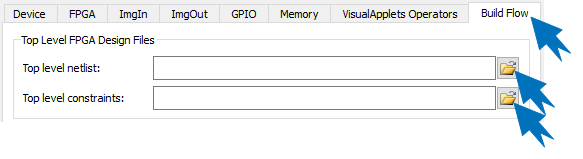
Go to the tab.
-
Under , enter the paths to the files you created:
Specify the path to your top level netlist (netlist of your overall FPGA design including wrapped VisualApplets core black box).
Specify the path to your user constraints file for your top level netlist (netlist of your overall FPGA design including wrapped VisualApplets core black box). If you use the Xilinx ISE tool chain, this is a
*.ucffile, if you use the Xilinx Vivado tool chain, this is an*.xdcfile. -
Under , specify the path to these files if required. Such files may be further netlists for additional IP cores with constraint files, etc.
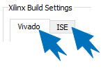
Under , you now need to specify the tool chain you will be using. Bitstream synthesis requires a 3rd party software: Depending on the used FPGA, this is either Xilinx Vivado WebPACK (free), Xilinx Vivado Design Suite, Xilinx ISE WebPACK (free), or Xilinx ISE Design Suite (registered trade marks of Xilinx Corp.).
-
Select the or tab, according to the Xilinx tool chain you use for synthesizing the FPGA bit stream.
-
Enter the details for your tool chain.
:
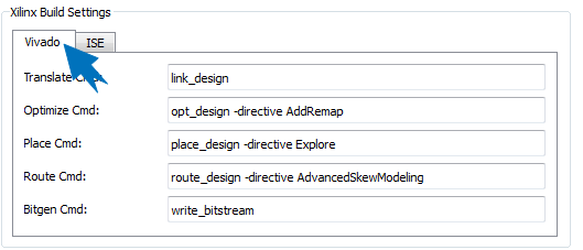
If you use Xilinx Vivado, provide the following details:
Command line for the link_design step of the Vivado implementation flow.
Command line for the opt_design step of the Vivado implementation flow.
Command line for the place_design step of the Vivado implementation flow.
Command line for the route_design step of the Vivado implementation flow.
Command line for the write_bitstream step of the Vivado implementation flow.
:
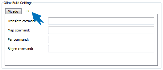
If you use Xilinx ISE, provide the following details:
Command line for the translate step of the ISE implementation flow.
Command line for the map step of the ISE implementation flow.
Command line for the place and route step of the ISE implementation flow.
Command line for the configuration bit stream generation step of the ISE implementation flow.
-
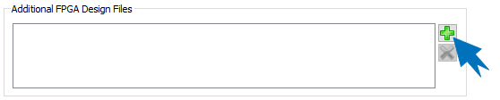
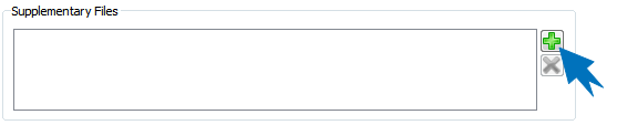
Under , enter additional files you want to have available in the hardware specific directory of VisualApplets if required. Such files might be user documentation, build flow plug-ins, scripts, documents, help tools, etc.
After you have entered all details regarding the build flow, you are ready to generate the eVA plugin installer for your target hardware.
The hardware-specific eVA plugin for VisualApplets is created out of the following files:
-
Mandatory:
-
Hardware description file (
*.xml), including operator definitions (see 'Defining Hardware-Specific Operators') -
Top-level netlist, including wrapped IP core black box (
*.ngc/*.edn) (see box below) -
Constraints file (
*.ucfformat if you use Xilinx ISE,*.xdcformat if you use Xilinx Vivado) (see box below)
-
-
Optional:
-
Icon file for the hardware device (
*.png) for graphical representation of hardware in VisualApplets GUI -
Icon files for the individual hardware-specific operators (
*.png) for graphical representation of operators in VisualApplets GUI -
Help files for the platform specific operators (
*.html)
-
All these files you have already entered to eVA Designer while working through the steps described in sections 'Defining the IP Core Properties' and 'Entering Build Flow Details'.
![[Note]](../common/images/admon/note.png) |
VisualApplets IP Core Netlist Generation |
|---|---|
|
You can also create a plugin installer without top-level netlist and constraints file. After installation, you will be able to see how the integration looks like in VisualApplets (available hardware-specific operators etc.). However, with a plugin that doesn’t contain the top-level netlist and constraints file, you cannot build applets that can run on your hardware platform. |
To build the actual eVA Plugin for VisualApplets, you have two options. You can either
-
Build and immediately install the eVA Plugin into the VisualApplets installation on your machine.
-
Build an executable eVA plugin installer which you can provide to colleagues and/or customers.
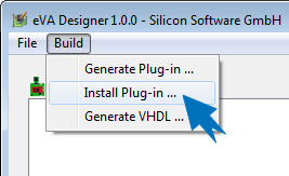
If you want to test or use the plug-in directly on the machine you have been developing it:
-
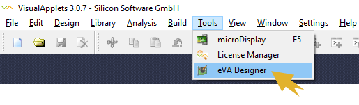
In , open the menu.
-
Select menu item
-
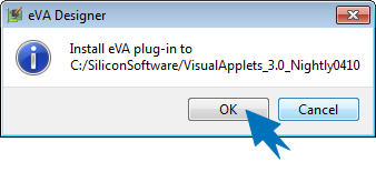
Enter the path to your VisualApplets installation directory, or confirm the suggested installation directory.
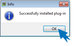
You are informed about the successful installation:
The files of the plug-in you find in the VisualApplets installation directory, subdirectory
eVA/platforms/<devicename>: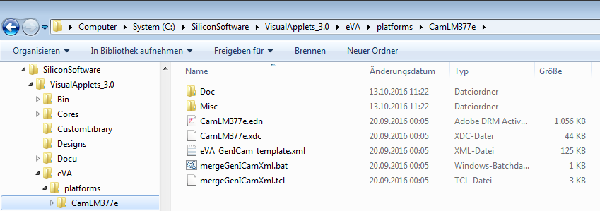
To create an executable that you can forward to VisualApplets developers that will design image processing applications for your hardware:
-
In , open the menu.
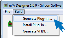
-
Select menu item
-
Select the target folder where you want to save the plugin.
As soon as you select the target folder, the eVA Plugin is created immediately. You are informed via message that your build was successful:
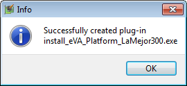
The plugin is available in the specified folder:
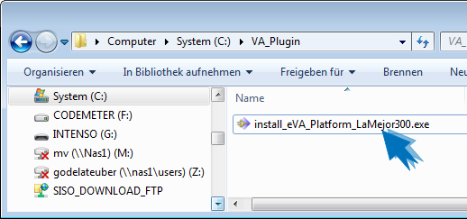
You can now distribute the plugin.
To install the eVA Plugin into an existing VisualApplets installation:
-
Close your VisualApplets installation.
-
Double-click the plugin
*.exefile in your file system. -
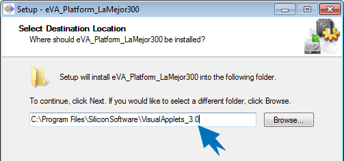
Follow the instructions of the installer. The installer automatically suggests the installation directory of VisualApplets:
-
Click to complete the installation process.
After installation, you can design new image processing applications for your platform in VisualApplets:
-
Open VisualApplets.
-
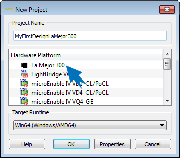
From menu File, select .
Now, you can select your hardware platform and start designing in VisualApplets:
For information how to design image acquisition and processing applications with VisualApplets, consult the comprehensive VisualApplets online Documentation at Getting Started.
