Operator Library: Blob
The Blob_Analysis_1D operator detects objects in binary images of infinite height and determines their properties. The outputs of the operator are several streams of data which represent properties for each object.
![[Note]](../common/images/admon/note.png) |
The Blob_Analysis_1D Is a Legacy Operator |
|---|---|
|
The Blob_Analysis_1D operator is a legacy operator, kept only for backward compatibility reasons. In new designs, use BlobDetector1D instead. |
|
You Might Need the 2D Operator Instead |
|---|---|
|
The Blob_Analysis_1D operator is used for acquisitions where objects are located in arbitrary positions. If in your line scan application your object positions can be determined with an image trigger, use the Blob_Analysis_2D operator instead. |
This operator reference manual includes the following information:
- Explanation of the operator's functionality
- Timing model for 1D applications
- Using the operator in the VisualApplets high level simulation
- Operator input and output ports
- I/O Properties
- Supported Link Formats
- パラメーター
- Examples of Use
For a general introduction into the blob analysis operators it is mandatory to read the introduction in Library Blob.
The Blob Analysis 1D operator is designed for endless one-dimensional images. In general, for 2D Blob Analysis, the object features are related to the position of the object in the frame and the coordinate point of origin is the top left corner of the image. This is not possible for 1D images with endless height. The objects cannot be related to a y-coordinate as this value would grow infinitely or cause an overflow.
The VisualApplets Blob Analysis 1D operator allows the use of endless images where objects may have any position. The operator is extended by a reference input "LineMarkerI" which the objects are related to. This may be counter values controlled by an external encoder and trigger pulse, for example. Using this method, it is possible to allocate each object determined by the blob analysis to the correct reference position.
The input link "FlushI" is used to flush the output, i.e., complete an output frame. For example, this is required to complete a DMA transfer.
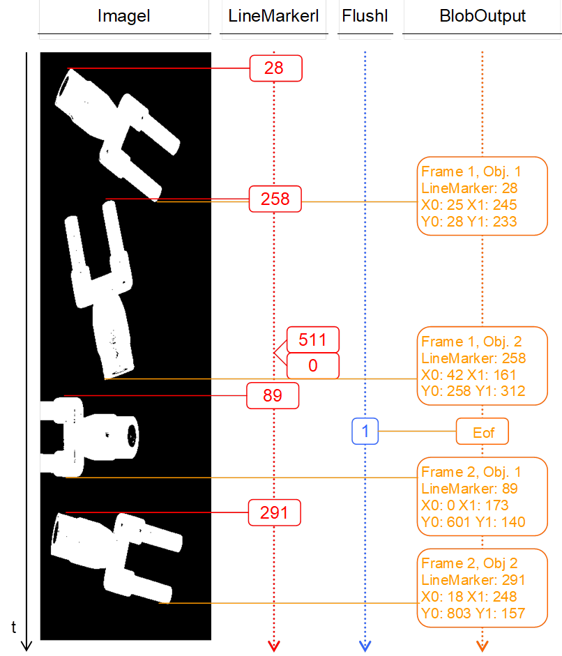
The following figure illustrates the behavior of the Blob Analysis 1D operator. It shows exemplified data at the input of the operator and the resulting output. The binary endless image processed by the Blob Analysis is shown on the left. The second column represents the LineMarkerI input. Here, a counter is used to mark the objects with reference values. For better visualization, only the values of interest are printed. The line marker input is assumed to have a bit width of nine bits. Hence, an overflow occurs at value 512. In the third column, the flush input is shown. In this example there is only one flush condition. The right column represents the output of the Blob Analysis operator. Looking at the example you see that the image together with the line marker is processed during Blob Analysis. As soon as an object is completed, it is output. The resulting object properties of all objects are marked with the line marker which was set together with the first image line of the respective object. The bounding box coordinates X0 and X1 are similar to the Blob Analysis 2D object features, whereas the Y1 coordinate is the height of the object. The Y0 coordinate results of an internal counter of the Blob Analysis 1D operator. It starts with zero and its maximum value is equal to the maximum height of objects set in the property dialog of the operator. The flush condition causes an end of frame flag at the output.
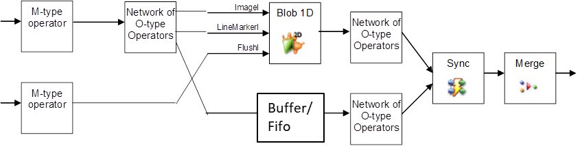
Similar to the 2D operator, the Blob Analysis 1D operator is of type "M" where all outputs are synchronous. In contrast to 2D, the 1D operator has three inputs. The first two inputs "ImageI" and "LineMarkerI" are synchronous and have to be sourced by the same M-type operator. The input link "FlushI" is asynchronous to the image and therefore does not need any synchronization. The following figure illustrates one possible configuration (amongst many others).
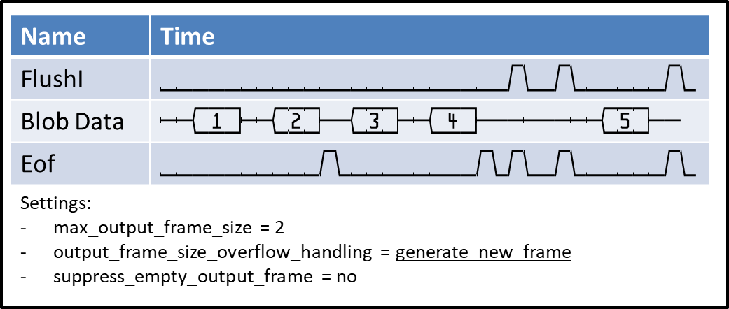
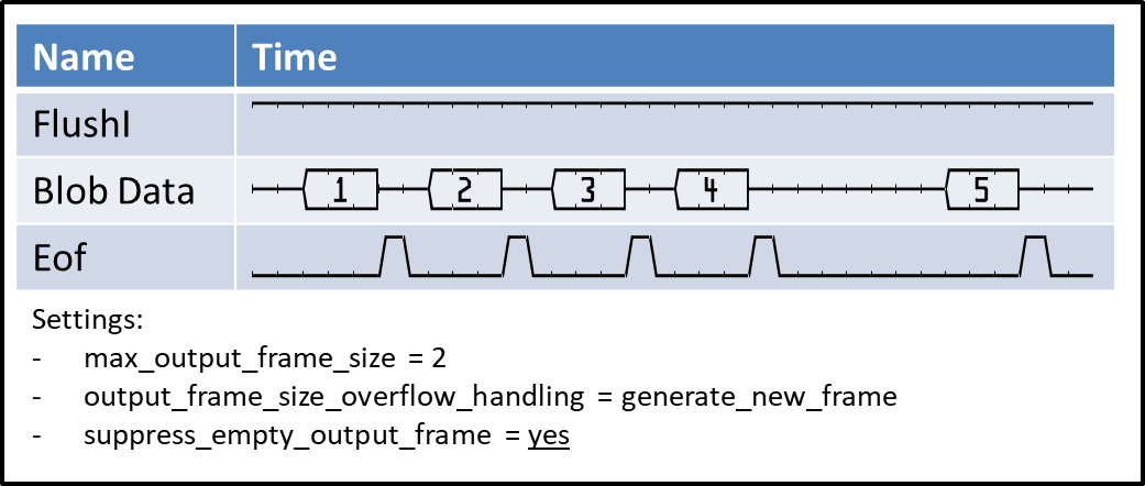
As mentioned above, the flush is used to finalize an output frame, i.e., to generate the end of frame flag. Depending on the timing of the flush input and the objects in the image, it could be possible to generate empty frames as well as output frames containing a lot of data. To control this behavior, parameters output_frame_size_overflow_handling and suppress_empty_output_frames (see parameter description below) are used. The following waveforms show sketches of different combinations of parameter settings, data, and flush input. The "Blob Data" represents the output timing.
The first example shows the generation of new frames after the maximum frame size has been reached. The blob operator generates an end of frame after the last blob has been output which completed the output frame. Flush signals will generate additional ends of frames:
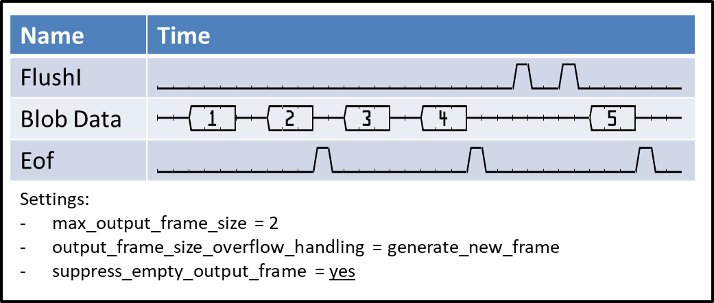
The next example shows the suppression of empty output frames. As you see, the first flush is ignored. The second flush is delayed until a blob is available for output. This way, the operator can delay flush outputs:
In the third example we see the behavior of a constant 1 at the flush input. As suppress_empty_output_frame is set to "yes", the operator will generate an end of frame after each blob output. Warning: If suppress_empty_output_frame is accidently set to "no", constant one can result in millions of ends of frames. If this output is connected to the VisualApplets output (DMA operator), it could cause a PC overload!
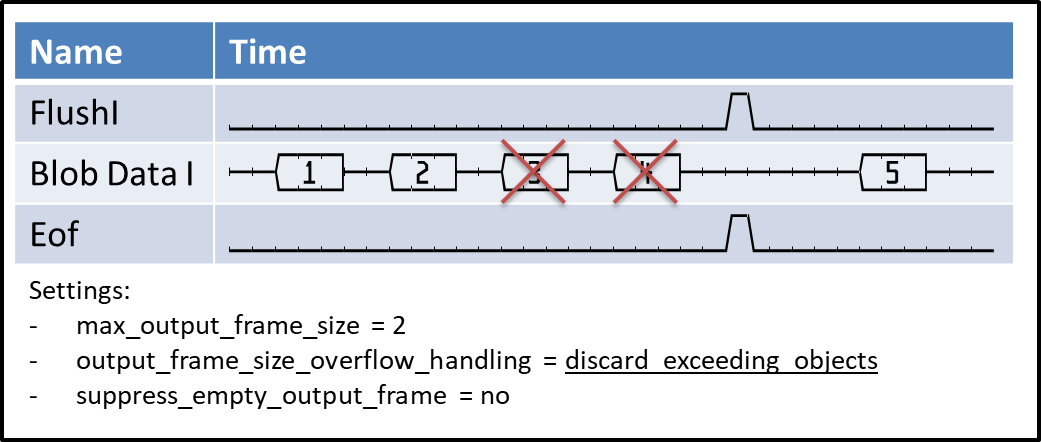
The last example shows the discarding of objects, as parameter "output_frame_size_overflow_handling" is set to "discard_exceeding_objects".
Please note that the output timing depends on the output pipeline. If data cannot be processed, i.e., the successive operators behind the blob operator block the processing, it might happen that flush signals are lost.
The VisualApplets blob analysis operators are some of the very few operators where the processing speed, i.e., the bandwidth, depends on the image content. Many objects in an image cause a large object list what may result in slowing down the operator input. This applies only for images containing very strong noise. For controlled conditions, the operator should be sufficiently fast.
The operator is designed to have a latency reduced to the minimum. Input images are transferred to the Blob Analysis line by line. If an object is completely transferred into the operator, its object features are output immediately once the operator can detect its completion. Hence, the Blob Analysis outputs objects as soon as they are completely transferred to the operator. The post-processing of the object features can be started while the image itself is still being processed.
Note that the DMA and some other operators wait for the frame end signal before they report completion. Check the description of the flush input to learn about frame end generation in the Blob_Analysis_1D operator.
![[Warning]](../common/images/admon/warning.png) |
Use the Simulation of Blob_Analysis_1D with Caution |
|---|---|
|
The Blob 1D simulation has some limitations. Please use the simulation feature with due caution. |
VisualApplets uses normal 2D images, even if the image protocol is 1D. So for simulating the operator, we use normal images. Each image is treated individually.
The simulation of the operator is NOT equal to the hardware behavior. There are two differences:
-
The order of the object feature output might differ in hardware and software. This is because the hardware output depends on the timing of the data which cannot be simulated in VisualApplets.
-
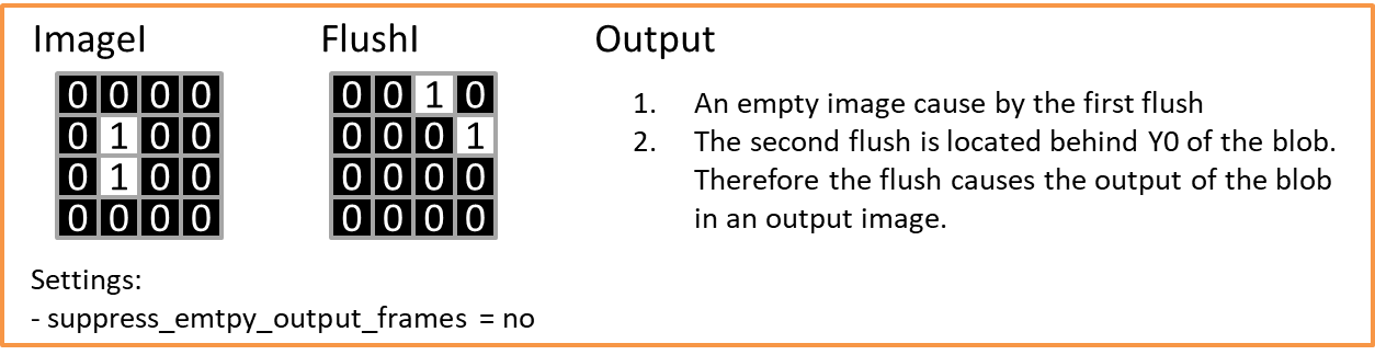
The second (and most important) difference is the behavior of the Flush conditions. The FlushI input is completely asynchronous to the image data input. FlushI is used to complete the output frames, i.e., it inserts end of frame markers into the output stream. (See above, and parameter description below.) As the flush is asynchronous to the image data, it cannot be simulated to reflect the same behavior as in hardware. Therefore, the VisualApplets simulation uses an alternative simulation model. As the behavior of the hardware cannot be copied, the simulation model is implemented differently to the hardware on purpose. It has the following properties:
-
The simulation tries to compare the correlation of the data input and the flush input by counting the pixels of both inputs. So if the data input and flush input have the same image dimensions, the correlation is 1:1 to the pixel position. However, if the flush input has less pixels (for example 1 pixel per line), only the simulation will compare the pixel positions.
-
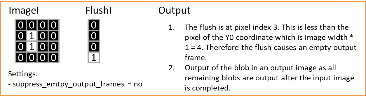
The flush condition will output an object in comparison to the Y0 coordinate of the object and not in comparison to its completion as done in hardware.
-
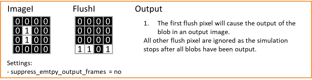
After the last object of an image has been output, all further flush signals are ignored. So in simulation, the number of flush signals at the input are not correlated to the number of frame outputs.
Because of this behavior, the simulation should be used with caution.
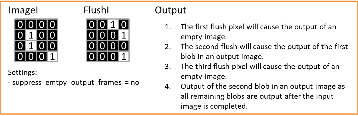
The following figures show some examples on mini-images, explaining some special conditions of using the flush signal in simulation.
-
The ImageI input of the Blob Analysis is represented by a binary one-dimensional image, i.e., an image having a bit width of 1 bit, a specified width, and an unlimited height. A parallelism of up to 32 pixels can be selected. Foreground values are assumed to have the value ONE, while background values must have the value ZERO. This must be considered at the binarization process.
As the LineMarkerI input is synchronous to the image data input, these links must have the same image dimensions and parallelism. However, the link may have any bit width. The value of LineMarker has to be constant throughout each image line.
The input link "FlushI" is asynchronous to the other input links. It may have any bit width, parallelism, and image dimensions. If one of the input bits of any of the parallel components is set, the Blob Analysis output is flushed.
Each of the output ports represents one object feature / object property. Each output value at these ports represents one object. Hence, the object properties result in a stream of data. The length of the output data streams is equal to the number of objects found in the image and can be interrupted into several sub-frames. Each output port has a height of 1 pixel and a specific length. They are represented as grayscale 2D images.
The output ports are configured by using the operator parameters and the properties of the input. The direct change of a link property is not possible.
The port ErrorFlagsO outputs several error flags of overflows. Each bit is reserved for a special flag. A detailed explanation can be found in the parameter description below. A summary is given in the following table:
| Bit # | 説明 | Object Related | 注意事項 |
|---|---|---|---|
| 0, 1 | label overflow | no |
The Blob Analysis has detected too many objects to store in memory. To increase the maximum number of objects within two image lines, operator parameter "LabelBits" can be changed. The flag is set upon detection until the end of the data output frame. All object properties which have been output so far are valid. For the Blob Analysis 1D operator, the flag has only high-level state for one clock cycle together with the next valid data output. After the flag is set, the output of the blob analysis might result in wrong object properties. The operator returns to correct functionality if enough object labels are available. |
| 2 | output truncated | yes |
The number of objects in the image exceeds the maximum output width set in the operator parameters dialog. The flag is set together with the last object which fits into the output width. |
| 3 | object size exceeds maximum | yes |
The flag is set if an object of the 1D Blob Analysis exceeds its maximum height. The operator will cut this exceeding object into smaller objects. The continuative object is marked with the flag to allow the detection of a cut. For 2D Blob Analysis the flag is set to constant zero. |
| 4 | area is truncated | yes |
The area of the object together with the error flag is larger than the area bits allow. |
| 5 | center of gravity X is truncated | yes |
The center of gravity in X-direction is larger than the bits allow. |
| 6 | center of gravity Y is truncated | yes |
The center of gravity in Y-direction is larger than the bits allow. |
| 7 | contour length overflow | yes |
The contour length is larger than the bits parameterized for the operator allow. |
Table 38. Explanation of Blob Error Flags
| Property | 値 |
|---|---|
| Operator Type | M |
| Input Links | ImageI, image data input LineMarkerI, data input FlushI, data input |
| Output Links | LineMarkerO, data output BoundingX0O, data output BoundingX1O, data output BoundingY0O, data output BoundingY1O, data output AreaO, data output CenterXO, data output CenterYO, data output ContourOrthoO, data output ContourDiaO, data output ErrorFlagsO, data output |
Synchronous and Asynchronous Inputs
- Synchronous Group: ImageI, LineMarkerI
- FlushI is asynchronous to the group.


|
|
The output bit width depends on the parameter settings of the object feature. If a feature is disabled, the output is set to one bit which is always value zero. |
|
|
The output maximum image width depends on the settings of parameter output_frame_size. |
| label_bits | |
|---|---|
| タイプ | static parameter |
| Default | 7 |
| 範囲 | [5, 31] |
|
This parameter sets the number of bits which are used to label the objects internally. It also influences the maximum number of objects which may coexist within two image lines determined by 2^label_bits. Note that the required memory resources for the blob analysis almost double with every additional bit. A good value range for this parameter is between 7 and 9 bits which should be sufficient for almost every application. If an overflow of this address space is detected, the operator outputs error flags at bits 0 and 1 of port "ErrorFlagsO". These flags are set upon detection of the overflow and are reset with the end of the output frame. |
|
| neighborhood | |
|---|---|
| タイプ | static parameter |
| Default | eight_connected |
| 範囲 | {four_connected, eight_connected} |
|
Selects the required neighborhood for object detection. See 'Definition' for a detailed explanation of pixel neighborhoods. |
|
| max_object_height_bits | |
|---|---|
| タイプ | static parameter |
| Default | 10 |
| 範囲 | [3, 31] |
|
This parameter is required to specify the maximum height of an object. For example, a height of 10 bits will not allow objects exceeding a height of 1024 image lines. If an object exceeds this limitation, it is cut into two ore more separated objects. If this happens, an error flag at bit number 3 of port ErrorFlagsO is set together with the resumed object. |
|
| max_output_frame_size | |
|---|---|
| タイプ | static parameter |
| Default | 65536 |
| 範囲 | [1, 67108864] |
|
Selects the maximum output frame size, i.e., the maximum number of objects in one output frame. |
|
| output_frame_size_overflow_handling | |
|---|---|
| タイプ | static parameter |
| Default | generate_new_frame |
| 範囲 | {generate_new_frame, discard_exceeding_objects} |
|
The maximum output frame size is specified with parameter "max_output_frame_size". If the number of objects exceeds this size, the operator can either generate a new frame or discard the exceeding objects. The generation of a new frame results in an end of frame, i.e., the frame is completed. If objects are discarded, the operator outputs an error flag at bit number 2 of port ErrorFlagsO together with the last valid object of the frame. Note that a new frame is also generated with the flush input. |
|
| suppress_empty_output_frames | |
|---|---|
| タイプ | static parameter |
| Default | yes |
| 範囲 | {yes, no} |
|
This parameter is used to suppress empty output frames caused by a flush condition and no object data. Detailed timing diagrams can be found in 'Generation of Output Frames - Flush, Empty Frames, Discarding Data'. |
|
| line_marker | |
|---|---|
| タイプ | static parameter |
| Default | used |
| 範囲 | {used, not_used} |
|
The "line_marker" of each object is output at "LineMarkerO". The bit width is determined by the input LineMarkerI input link. If the line marker is not used, the bit width is set to one with constant zero at its output. |
|
| bounding_box_x0 | |
|---|---|
| タイプ | static parameter |
| Default | used |
| 範囲 | {used, not_used} |
|
A bounding box represents the minimum paraxial rectangle which fits over the object. Each coordinate value is relatively to the top left corner of the image. The bounding box X0 represents the lowest x-coordinate of each object. It is output at "BoundingX0O". The bit width is determined by the input image. If the bounding box is not used, the bit width is set to one bit with constant zero at its output. |
|
| bounding_box_x1 | |
|---|---|
| タイプ | static parameter |
| Default | used |
| 範囲 | {used, not_used} |
|
A bounding box represents the minimum paraxial rectangle which fits over the object. Each coordinate value is relatively to the top left corner of the image. The bounding box X1 represents the highest x-coordinate of each object. It is output at "BoundingX1O". The bit width is determined from the input image. If the bounding box is not used, the bit width is set to one bit with constant zero at its output. |
|
| bounding_box_y0 | |
|---|---|
| タイプ | static parameter |
| Default | used |
| 範囲 | {used, not_used} |
|
The bounding box y0 represents the lowest y-coordinate of each object. This coordinate is based on an internal counter of the operator. It starts counting with the first image line processed. Its maximum value is equal to the maximum height set with the parameter max_object_height_bits. After an overflow, the counter starts from zero again. This feature can be used instead of the line marker. However, the line marker offers more possibilities and allows complex configurations. The feature is output at "BoundingY0O". The bit width is determined by the input image. If the bounding box is not used, the bit width is set to one with constant zero at its output. |
|
| bounding_box_y1 | |
|---|---|
| タイプ | static parameter |
| Default | used |
| 範囲 | {used, not_used} |
|
With the 1D operator (in contrast to the 2D operator), bounding box y1 represents the height of an object. It is output at "BoundingY1O". The bit width is determined by the input image. If the bounding box is not used, the bit width is set to one with constant zero at its output. |
|
| area_mode | |
|---|---|
| タイプ | static parameter |
| Default | use_area_with_maximum_required_bits |
| 範囲 | {area_not_used, use_area_with_maximum_required_bits, use_area_with_specified_bits} |
|
The area of an object is defined by the sum of all object foreground pixels. This parameter is used to select the required area mode. If "use_area_with_maximum_required_bits" is selected, the operator will automatically determine the required bits for the maximum possible size of an object. The maximum possible size of an object depends on the maximum width and height at the input link I. The theoretical maximum of an object is achieved if all pixels of an image consist of foreground values, i.e., a white input image which is one large object. If users can be sure that objects will not have a larger area than a specified value, this can be parameterized. Select "use_area_with_specified_bits" if the maximum object size is known. Use parameter "area_bits" to specify the number of bits. If the area is not required at all, select "area_not_used". In "area_not_used" mode, the bit width is set to one with constant zero at its output. |
|
| area_bits | |
|---|---|
| タイプ | static parameter |
| Default | not_used |
| 範囲 | {not_used, used} |
|
This parameter is enabled only if parameter "area_mode" is set to "use_area_with_specified_bits". If the area of an object is larger than the selected bits allow for, the blob analysis will output an overflow flag at bit number 4 of the output link "ErrorFlagsO". |
|
| center_of_gravity_x_mode | |
|---|---|
| タイプ | static parameter |
| Default | use_cX_with_maximum_required_bits |
| 範囲 | {cX_not_used, use_cX_with_maximum_required_bits, use_cX_with_specified_bits} |
|
See 'Center of Gravity' for an explanation of the center of gravity. Note that the output has to be divided by the area after blob analysis to get correct results. If the parameter is set to "use_cX_width_maximum_required_bits", the operator will determine the output bits automatically. The required number of bits can get very high if large input images are used. The number of bits is adjustable if "use_cX_with_specified_bits" is used for parameter value. If no center of gravity in x-direction is required, it can be switched off by selecting "cX_not_used". |
|
| center_of_gravity_x_bits | |
|---|---|
| タイプ | static parameter |
| Default | 29 |
| 範囲 | [2, auto] |
|
If "use_cX_with_specified_bits" is set for "center_of_gravity_x_mode", the bits can be changed here. Otherwise, the parameter is disabled. |
|
| center_of_gravity_x_overflow_flag | |
|---|---|
| タイプ | static parameter |
| Default | not_used |
| 範囲 | {not_used, used} |
|
If the number of bits for the center of gravity in x-direction is set manually, this parameter is activated and can be set to "used". The operator will then output a ONE at bit number 5 of the output link "ErrorFlagsO" if an overflow is detected. |
|
| center_of_gravity_y_mode | |
|---|---|
| タイプ | static parameter |
| Default | use_cY_with_maximum_required_bits |
| 範囲 | {cY_not_used, use_cY_with_maximum_required_bits, use_cY_with_specified_bits} |
|
See 'Center of Gravity' for an explanation of the center of gravity. Note that the output has to be divided by the area after blob analysis to get correct results. If the parameter is set to "use_cY_width_maximum_required_bits", the operator will determine the output bits automatically. The required number of bits can get very high if large input images are used. The number of bits is adjustable if "use_cY_with_specified_bits" is used for parameter value. If no center of gravity in y-direction is required, it can be switched off by selecting "cY_not_used". |
|
| center_of_gravity_y_bits | |
|---|---|
| タイプ | static parameter |
| Default | 29 |
| 範囲 | [2, auto] |
|
If "use_cY_with_specified_bits" is set for "center_of_gravity_y_mode", the bits can be changed here. Otherwise, the parameter is disabled. |
|
| center_of_gravity_y_overflow_flag | |
|---|---|
| タイプ | static parameter |
| Default | not_used |
| 範囲 | {not_used, used} |
|
If the number of bits for the center of gravity in y-direction is set manually, this parameter is activated and can be set to "used". The operator will then output a ONE at bit number 6 of the output link "ErrorFlagsO" if an overflow is detected. |
|
| contour_length_mode | |
|---|---|
| タイプ | static parameter |
| Default | contour_length_not_used |
| 範囲 | {contour_length_not_used, contour_length_used} |
|
The contour length of an object includes all edges, even at holes. For a detailed explanation see 'Contour Length'. If this feature is selected, the required bits can be chosen with the parameters "contour_length_bits_orthogonal_connected" and "contour_length_bits_diagonal_connected" depending on the neighborhood selected. If a 4-connected neighborhood is selected, the contour length can only be determined in orthogonal directions. If an 8-connected neighborhood is selected the contour length is determined in orthogonal and diagonal directions. |
|
| contour_length_bits_orthogonal_connected | |
|---|---|
| タイプ | static parameter |
| Default | 16 |
| 範囲 | [1, 31] |
|
If "contour_length_mode" is set to "contour_length_used", the bits required to represent the contour length for orthogonal connected pixels can be chosen here. |
|
| contour_length_bits_diagonal_connected | |
|---|---|
| タイプ | static parameter |
| Default | 16 |
| 範囲 | [1, 31] |
|
If "contour_length_mode" is set to "contour_length_used", the bits required to represent the contour length for diagonal connected pixels can be chosen here. This is only possible if an 8-connceted neighborhood is selected. Otherwise, this parameter is disabled. |
|
| contour_length_overflow_flag | |
|---|---|
| タイプ | static parameter |
| Default | not_used |
| 範囲 | {not_used, used} |
|
The contour length may cause an overflow. If the flag is used, an error flag is set at bit number 7 of port "ErrorFlagsO" in case of an overflow. |
|
The use of operator Blob_Analysis_1D is shown in the following examples:
-
Examples - Shows the usage of operator Blob_Analysis_1D in line scan applications.
