Operator Library: Hardware Platform
The GPO operator provides an interface to the digital outputs. Via the Pin_ID / PinID parameter (the name of the parameter depends on the hardware platform), you select the digital output (which is wired to a physical pin on a GPIO unit) you want to use for sending a signal.
For all platforms except the imaFlex platforms: If you use a frame grabber with two GPIO units, use the ConnectorType parameter to select the GPIO unit you want to address (GPIO or Front GPIO). On the imaFlex 2 Dual 100, imaFlex CXP-12 Quad and imaFlex CXP-12 Penta platforms, the ConnectorType parameter is not available.
Each digital output can only be used once. Thus, the selected digital output is to be used by exclusively one instance of the GPO operator.
![[Note]](../common/images/admon/note.png) |
Front GPO Port Groups on the imaFlex 2 Dual 100 Platform |
|---|---|
|
The front GPO ports on the imaFlex 2 Dual 100 platform are divided into two independent groups:
|
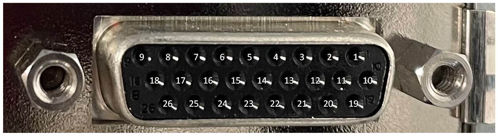
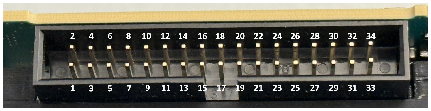
For the mapping of digital inputs and pin connectors, see the GPIO Connectors topic of your frame grabber User Manual. For the imaFlex 2 Dual 100 plaform, see GPIO Connectors (CoF Frame Grabbers).
| Available for Hardware Platforms |
|---|
| imaFlex 2 Dual 100 |
| imaFlex CXP-12 Penta |
| imaFlex CXP-12 Quad |
| mE 5 marathon VCLx |
| mE 5 marathon VCL |
| mE 5 marathon VCX-QP |
| mE 5 marathon VF2 |
| LightBridge VCL |
| mE 5 ironman VQ8-CXP6D/-CXP6B |
| mE 5 ironman VD8-PoCL |
| pixelPlant 100 |
| pixelPlant 200 |
Resources
The FPGA device resources of this operator are equal to value of the PinID parameter. You can see the FPGA device resources, if you open the dialog from the menu. The device resources are read-only:
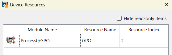
For the imaFlex 2 Dual 100 platform, the resource is of type GPO with index 0 to 7 for Front GPIO connector and 8 to 15 – for the Extension GPIO connector.
For each digital output, one device resource of type TriggerOut is used. See Device Resources for a full list of device resources.
| Property | 値 |
|---|---|
| Operator Type | M |
| Input Link | I, general purpose output signal to be send out of the frame grabber. |
| Link Parameter | Input Link I |
|---|---|
| Bit Width | 1 |
| Arithmetic | unsigned |
| Parallelism | 1 |
| Kernel Columns | 1 |
| Kernel Rows | 1 |
| Img Protocol | VALT_SIGNAL |
| Color Format | VAF_GRAY |
| Color Flavor | FL_NONE |
| Max. Img Width | any |
| Max. Img Height | any |
| PinID (all imaFlex platforms) | ||||||||||||||||||||||||||||||||||||||||||||||||||||
|---|---|---|---|---|---|---|---|---|---|---|---|---|---|---|---|---|---|---|---|---|---|---|---|---|---|---|---|---|---|---|---|---|---|---|---|---|---|---|---|---|---|---|---|---|---|---|---|---|---|---|---|---|
| タイプ | static write parameter | |||||||||||||||||||||||||||||||||||||||||||||||||||
| Default | FrontGpo0 | |||||||||||||||||||||||||||||||||||||||||||||||||||
| 範囲 |
imaFlex 2 Dual 100: {FrontGpo0, FrontGpo1, FrontGpo2, FrontGpo3, FrontGpo4, FrontGpo5, FrontGpo6, FrontGpo7, ExtensionGpo0, ExtensionGpo1, ExtensionGpo2, ExtensionGpo3, ExtensionGpo4, ExtensionGpo5, ExtensionGpo6, ExtensionGpo7} imaFlex CXP-12 Penta: {FrontGpo0, FrontGpo1, FrontGpo2, FrontGpo3, ExtensionGpo0, ExtensionGpo1, ExtensionGpo2, ExtensionGpo3, ExtensionGpo4, ExtensionGpo5, ExtensionGpo6, ExtensionGpo7} imaFlex CXP-12 Quad:{FrontGpo0, FrontGpo1, ExtensionGpo0, ExtensionGpo1, ExtensionGpo2, ExtensionGpo3, ExtensionGpo4, ExtensionGpo5, ExtensionGpo6, ExtensionGpo7} |
|||||||||||||||||||||||||||||||||||||||||||||||||||
|
Via the PinID parameter, you define the digital output (which is wired to a physical pin on a GPIO socket) you want to use for sending a signal. The same digital output can be used only once, i.e., by one instance of the GPO operator. FrontGpoN represents the GPO for the Front GPIO connector. ExtensionGpoN represents the GPO for Extension GPIO side connector. For the mapping of digital inputs and pin connectors, see the GPIO Connectors topic of your frame grabber User Manual. For the imaFlex 2 Dual 100 plaform, see GPIO Connectors (CoF Frame Grabbers).
|
||||||||||||||||||||||||||||||||||||||||||||||||||||
| Pin_ID (mE5 platforms, pixelPlant and LightBridge VCL) | ||||
|---|---|---|---|---|
| タイプ | static write parameter | |||
| Default | 0 | |||
| 範囲 | [0;7], [0;3] or [0;1] | |||
|
Via parameter Pin_ID, you define the digital ouput (which is wired to a physical pin on the GPIO or FrontGPIO socket) you want to use for sending a signal. The same digital output can be used only once, i.e., by one instance of the GPO operator. [0;7] When you address the GPIO on marathon, or if you use a device with only one GPIO unit (ironman, PixelPlant), the value range is 0 - 7. [0;3] When you address the GPIO on LightBridge, the value range is 0-3. [0;1] When you address the Front GPIO on marathon or LightBridge, the value range is 0-1.
|
||||
| ConnectorType (mE5 marathon and LightBridge VCL platforms) | ||||
|---|---|---|---|---|
| タイプ | static write parameter | |||
| Default | GPIO | |||
| 範囲 | {GPIO, FrontGPIO} | |||
|
Via parameter ConnectorType, you define which GPIO socket (GPIO or Front GPIO) you want to address with the value you enter for parameter Pin_ID.
|
||||
The use of operator GPO is shown in the following examples:
-
'Area Scan Trigger for microEnable 5 marathon VCX QP'
An area scan trigger for CoaXPress is presented. External sources, an internal frequency generator or software trigger pulses can be used for trigger generation.
-
'Area Scan Trigger for imaFlex CXP-12 Quad'
An area scan trigger for CoaXPress12 is presented. External sources, an internal frequency generator or software trigger pulses can be used for trigger generation.
-
' Line Scan Trigger for microEnable 5 marathon VCL with TrgBoxLine Operator Usage'
A VisualApplets design example showing the usage of operator TrgBoxLine in a simple design.
-
'Line Scan Trigger for microEnable 5 marathon VCX QP with TrgBoxLine Operator Usage'
A VisualApplets design example showing the usage of operator TrgBoxLine in a simple design.
-
'Line Scan Trigger for imaFlex CXP-12 Quad with TrgBoxLine Operator Usage'
A VisualApplets design example showing the usage of operator TrgBoxLine in a simple design.
