TDI (Time Delay Integration)#
TDI は光感度を高め、より広いダイナミックレンジを持つ明るい画像を生成するため、低照度環境での使用に最適です。
情報
この機能は、Basler racer 2 XL カメラおよび racer 2 L mono カメラでのみ使用できます。
機能を使用する#
この機能の実装はカメラによって異なります。
racer 2 XL カメラ#
racer 2 XL カメラには、TDI センサーが搭載されています。TDI センサーは、ステージと呼ばれる複数のピクセル行がアレイ状に配置されて構成されています。
被写体がセンサーの視野内を移動すると、その画像は最初のステージの露光エリアから最後のステージの露光エリアへと投影されます。各ステージが個別に順番に露光されるのではなく、ブロック全体として露光されます。つまり、センサーはどのステージでも同じ被写体を露光し、電荷が読み出しラインに到達するまで電荷の蓄積と転送を行います。
次の図は、4つのステージを持つセンサー内の電荷転送を示しています。
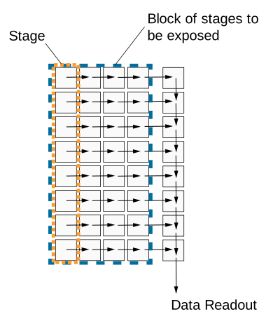
あるステージから次のステージへの電荷転送は、被写体の移動と正確に同期している必要があります。これにより、継続的な露光と電荷の統合が確保されます。被写体の露光は、それがカメラの視野内にある間続きます。使用するステージ数が多いほど、実効的な Exposure Time および統合時間が長くなります。
次の図は、TDI センサーの視野とその電荷シフトの原理を示しています。
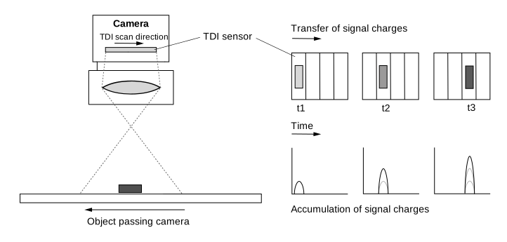
Number Of Stages#
ステージ数は、最後のステージに到達するまでに電荷が蓄積され、あるステージから次のステージへシフトされる頻度を決定します。ステージ数が多いほど、画像の感度が高くなります。たとえば、ステージ数が 256 の場合、カメラは 256 倍高い感度で画像を取得します。ステージ数は、結果として得られる Exposure Time にも影響します。
センサーは、4 ステージや最大 256 ステージなど、さまざまなステージ数で動作するように設定できます。利用可能なステージ数は、使用するセンサーによって異なります。
ステージ数を設定するには、 BslTDINumberOfStages パラメータ値を次のように設定します。例: Stages4 または Stages256.
情報
Area sensor acquisition mode では、ステージ数によって画像高さが決まります。たとえば、ステージ数を 128 に設定した場合、r2T16416-500cm カメラは Area sensor acquisition mode で 16416 x 128 の「エリア」画像を取得します。
Scan Direction#
TDI センサーのスキャン方向は、カメラを通過する被写体の移動と同期させる必要があります。継続的な露光と電荷の統合を確実にするため、スキャン方向は被写体が移動している方向と同じである必要があります。
情報
スキャン方向の設定方法の説明では、カメラにレンズが装着されていることを前提としています。レンズによって画像が反転します。
スキャン方向を設定するには、以下のように設定します。 BslTDIScanDirection パラメーターを次のいずれかの値に設定します。
Forward:センサーの視野を通過するオブジェクトは、 前進 スキャン方向でスキャンされます。オブジェクトは最初にカメラの下部を通過し、次に上部を通過します。Reverse:センサーの視野を通過するオブジェクトは、 逆 スキャン方向。オブジェクトは最初にカメラの上部を通過し、次に下部を通過します。
Resulting Exposure Time#
TDI センサー取得モードでは、Exposure Timeは ExposureTime Propertyを介して設定されません。代わりに、次の2つの取得パラメータから算出されます。
- Number of stages:電荷の蓄積と転送が行われている間に、オブジェクトがセンサーの視野にとどまる時間を定義します。
- Line rate:あるステージから次のステージへ電荷が転送される速度を定義します。また、個々のステージあたりの露光時間も決定します。
これら2つのパラメータを合わせることで、総Exposure Timeが決定されます。
$$ \text{Exposure time} = \frac{\text{Number of stages}}{\text{Line rate}} $$
次の表に、500 kHzの固定Line rateおよびさまざまなNumber of stagesにおけるExposure Timeの例を示します。
| Number of Stages | Line Rate [kHz] | Exposure Time [µs] |
|---|---|---|
| 4 | 500 | 8 |
| 64 | 500 | 128 |
| 128 | 500 | 256 |
| 256 | 500 | 512 |
次の表に、128ステージの固定数および最大500 kHzまでのさまざまなLine rateにおけるExposure Timeの例を示します。
| Line Rate [kHz] | Number of Stages | Exposure Time [µs] |
|---|---|---|
| 100 | 128 | 1280 |
| 200 | 128 | 640 |
| 400 | 128 | 320 |
| 500 | 128 | 256 |
Number of stagesとLine rateはいずれもExposure Timeに影響を与えるため、トリガーがオブジェクトの動きと正しく同期され、ピクセルの飽和限界が守られているという条件のもとで、画像の明るさにも影響を与えます。
- Number of stagesを高くすると、Exposure Timeが長くなり、その結果、蓄積される電荷が増加します。画像は明るく表示されます。
- Number of stagesを低くすると、Exposure Timeが短くなり、その結果、蓄積される電荷が減少します。画像は暗く表示されます。
- Line rateを高くすると、ステージあたりのExposure Timeが短くなり、その結果、蓄積される電荷が減少します。画像は暗く表示されます。
- Line rateを低くすると、ステージあたりのExposure Timeが長くなり、その結果、蓄積される電荷が増加します。画像は明るく表示されます。
racer 2 XL カメラでの TDI の設定#
racer 2 XLカメラをTDI用に設定するには:
- パラメーターを
BslSensorAcquisitionModeパラメータをTDISingleLine。センサーは1つの読み出しラインを使用します。 - システム構成に応じて、次のパラメータを設定します:
BslTDIScanDirectionパラメータ(例:Forward. - パラメーターを
BslTDINumberOfStagesパラメータ(例:128)。
情報
- センサーの読み出し手順が、対象物の移動速度および移動方向と正確に同期していることを確認してください。テスト目的で、それに応じてAcquisition Line Rateを変更します。これにより、結果として得られるExposure Timeにも影響が及びます。
- トリガー一時停止の後に再トリガーを行う場合、少なくとも最初のn個の読み出しラインが無効と見なされる必要があります。ここで、nはステージの最小数を表します。
racer 2 L Mono カメラ#
racer 2 L mono camerasには、マルチラインセンサー(デュアルラインまたはクアッドラインセンサー)が搭載されています。センサーの各ピクセルラインは、異なるExposure Timeで露光されるように設定できます。取り込み(アクイジション)がトリガーされると、センサーのすべてのピクセルラインが同時に露光されます。1回の露光において、センサー内の各ラインは、カメラの前を通過する対象物に対する視野(フィールドオブビュー)がそれぞれ異なるため、対象物上の異なる領域を取り込みます。
次の図は、モノクロクアッドラインセンサーの視野を示しています。
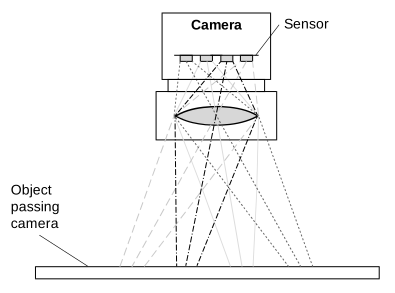
この場合、対象物上の特定の領域に関する完全な情報を得るために、4つの異なる取り込みからのデータをバッファリングして結合する必要があります。これを行うのがSpatial Correctionです。今回の露光における最後のラインのデータは、過去の露光から取得された前回のラインのデータと結合されます。
Line Combination Modeを使用すると、HDR画像を取得するために個々のラインのピクセル値を結合する方法を最終的に指定できます。
Line Combination Mode#
Line Combination Modeを使用すると、結合されたセンサーラインのピクセル値を加算するか平均化するかを定義できます。次のように設定できます: BslLineCombinationMode パラメーターを次のいずれかの値に設定します。
Off:ラインの結合が無効になります。TDISum:結合されたセンサーラインのピクセル値が加算されます。これにより、カメラの光に対する感度とS/N比が向上します。TDIAverage:結合されたセンサーラインのピクセル値が平均化されます。これにより、カメラの光に対する感度に影響を与えることなく、S/N比が向上します。
racer 2 L mono カメラでの TDI の設定#
racer 2 L monoカメラをTDI用に設定するには:
- パラメーターを センサー取得モード デュアルまたはクアッドライン画像取り込みに設定します:
パラメーターをBslSensorAcquisitionModeパラメータをDualLineまたはQuadLineTDI用に2つまたは4つのラインのどちらを使用するかによって異なります。 -
各ライン(ステージ)のExposure Timeを指定します:
- パラメーターを
ExposureTimeModeパラメータをIndividual. - パラメーターを
ExposureTimeSelectorパラメータをStage1. - パラメーターを
ExposureTimeパラメータを目的の Exposure Time (マイクロ秒) に設定します。
注記: カメラモデルの最小および最大のExposure Time値は、次の場所で確認できます: 特性 セクション: Exposure Time トピックを参照してください。 - 他のステージについても、ステップbとcを繰り返します。
- パラメーターを
-
次を指定します: Spatial Correction Stride Spatial Correctionの開始ラインと方向を決定します:
パラメーターをBslSpatialCorrectionStrideパラメータ(例:2)。 - パラメーターを ライン結合モード 結合されたラインのセンサーピクセル値が合計されるか、平均化されるかを決定します。
パラメーターをBslLineCombinationModeパラメータ(例:TDIAverage.
外部の後処理プログラムを使用してライン情報を結合し、高ダイナミックレンジ画像を生成します。
サンプルコード#
racer 2 XL カメラ#
// Set the sensor acquisition mode to TDI Single Line
camera.BslSensorAcquisitionMode.SetValue(BslSensorAcquisitionMode_TDISingleLine);
// Set the sensor scan direction to Forward
camera.BslTDIScanDirection.SetValue(BslTDIScanDirection_Forward);
// Set the number of stages to 128
camera.BslTDINumberOfStages.SetValue(BslTDINumberOfStages_128);
INodeMap& nodemap = camera.GetNodeMap();
// Set the sensor acquisition mode to TDI Single Line
CEnumParameter(nodemap, "BslSensorAcquisitionMode").SetValue("TDISingleLine");
// Set the sensor scan direction to Forward
CEnumParameter(nodemap, "BslTDIScanDirection").SetValue("Forward");
// Set the number of stages to 128
CEnumParameter(nodemap, "BslTDINumberOfStages").SetValue("");
// Set the sensor acquisition mode to TDI Single Line
camera.Parameters[PLCamera.BslSensorAcquisitionMode].SetValue(PLCamera.BslSensorAcquisitionMode.TDISingleLine);
// Set the sensor scan direction to Forward
camera.Parameters[PLCamera.BslTDIScanDirection].SetValue(PLCamera.BslTDIScanDirection.Forward);
// Set the number of stages to 128
camera.Parameters[PLCamera.BslTDINumberOfStages].SetValue(PLCamera.BslTDINumberOfStages.);
/* Macro to check for errors */
#define CHECK(errc) if (GENAPI_E_OK != errc) printErrorAndExit(errc)
GENAPIC_RESULT errRes = GENAPI_E_OK;  /* Return value of pylon methods */
/* Set the sensor acquisition mode to TDI Single Line */
errRes = PylonDeviceFeatureFromString(hdev, "BslSensorAcquisitionMode", "TDISingleLine");
CHECK(errRes);
/* Set the sensor scan direction to Forward */
errRes = PylonDeviceFeatureFromString(hdev, "BslTDIScanDirection", "Forward");
CHECK(errRes);
/* Set the number of stages to 128 */
errRes = PylonDeviceFeatureFromString(hdev, "BslTDINumberOfStages", "");
CHECK(errRes);
racer 2 L Mono カメラ#
// Set the sensor acquisition mode to Dual Line
camera.BslSensorAcquisitionMode.SetValue(BslSensorAcquisitionMode_DualLine);
// Set the exposure time for both lines (stages)
// Select stage 1
camera.ExposureTimeSelector.SetValue(ExposureTimeSelector_Stage1);
// Set the exposure time to 1000 microseconds
camera.ExposureTime.SetValue(1000.0);
// Select stage 2
camera.ExposureTimeSelector.SetValue(ExposureTimeSelector_Stage2);
// Set the exposure time to 1000000 microseconds
camera.ExposureTime.SetValue(1000000.0);
// Set the spatial correction stride to 2
camera.BslSpatialCorrectionStride.SetValue(BslSpatialCorrectionStride_2);
// Set the line combination mode to TDI Sum
camera.BslLineCombinationMode.SetValue(BslLineCombinationMode_TDISum);
INodeMap& nodemap = camera.GetNodeMap();
// Set the sensor acquisition mode to Dual Line
CEnumParameter(nodemap, "BslSensorAcquisitionMode").SetValue("DualLine");
// Set the exposure time for both lines (stages)
// Select stage 1
CEnumParameter(nodemap, "ExposureTimeSelector").SetValue("Stage1");
// Set the exposure time to 1000 microseconds
CFloatParameter(nodemap, "ExposureTime").SetValue(1000.0);
// Select stage 2
CEnumParameter(nodemap, "ExposureTimeSelector").SetValue("Stage2");
// Set the exposure time to 1000000 microseconds
CFloatParameter(nodemap, "ExposureTime").SetValue(1000000.0);
// Set the spatial correction stride to 2
CEnumParameter(nodemap, "BslSpatialCorrectionStride").SetValue("");
// Set the line combination mode to TDI Sum
CEnumParameter(nodemap, "BslLineCombinationMode").SetValue("TDISum");
// Set the sensor acquisition mode to Dual Line
camera.Parameters[PLCamera.BslSensorAcquisitionMode].SetValue(PLCamera.BslSensorAcquisitionMode.DualLine);
// Set the exposure time for both lines (stages)
// Select stage 1
camera.Parameters[PLCamera.ExposureTimeSelector].SetValue(PLCamera.ExposureTimeSelector.Stage1);
// Set the exposure time to 1000 microseconds
camera.Parameters[PLCamera.ExposureTime].SetValue(1000.0);
// Select stage 2
camera.Parameters[PLCamera.ExposureTimeSelector].SetValue(PLCamera.ExposureTimeSelector.Stage2);
// Set the exposure time to 1000000 microseconds
camera.Parameters[PLCamera.ExposureTime].SetValue(1000000.0);
// Set the spatial correction stride to 2
camera.Parameters[PLCamera.BslSpatialCorrectionStride].SetValue(PLCamera.BslSpatialCorrectionStride.);
// Set the line combination mode to TDI Sum
camera.Parameters[PLCamera.BslLineCombinationMode].SetValue(PLCamera.BslLineCombinationMode.TDISum);
/* Macro to check for errors */
#define CHECK(errc) if (GENAPI_E_OK != errc) printErrorAndExit(errc)
GENAPIC_RESULT errRes = GENAPI_E_OK;  /* Return value of pylon methods */
/* Set the sensor acquisition mode to Dual Line */
errRes = PylonDeviceFeatureFromString(hdev, "BslSensorAcquisitionMode", "DualLine");
CHECK(errRes);
/* Set the exposure time for both lines (stages) */
/* Select stage 1 */
errRes = PylonDeviceFeatureFromString(hdev, "ExposureTimeSelector", "Stage1");
CHECK(errRes);
/* Set the exposure time to 1000 microseconds */
errRes = PylonDeviceSetFloatFeature(hdev, "ExposureTime", 1000.0);
CHECK(errRes);
/* Select stage 2 */
errRes = PylonDeviceFeatureFromString(hdev, "ExposureTimeSelector", "Stage2");
CHECK(errRes);
/* Set the exposure time to 1000000 microseconds */
errRes = PylonDeviceSetFloatFeature(hdev, "ExposureTime", 1000000.0);
CHECK(errRes);
/* Set the spatial correction stride to 2 */
errRes = PylonDeviceFeatureFromString(hdev, "BslSpatialCorrectionStride", "");
CHECK(errRes);
/* Set the line combination mode to TDI Sum */
errRes = PylonDeviceFeatureFromString(hdev, "BslLineCombinationMode", "TDISum");
CHECK(errRes);
# Set the sensor acquisition mode to Dual Line
camera.BslSensorAcquisitionMode.Value = "DualLine"
# Set the exposure time for both lines (stages)
# Select stage 1
camera.ExposureTimeSelector.Value = "Stage1"
# Set the exposure time to 1000 microseconds
camera.ExposureTime.Value = 1000.0
# Select stage 2
camera.ExposureTimeSelector.Value = "Stage2"
# Set the exposure time to 1000000 microseconds
camera.ExposureTime.Value = 1000000.0
# Set the spatial correction stride to 2
camera.BslSpatialCorrectionStride.Value = ""
# Set the line combination mode to TDI Sum
camera.BslLineCombinationMode.Value = "TDISum"
pylon Viewerを使用して、パラメーターを簡単に設定することもできます。