Configuring CXP Line Scan Cameras and Frame Grabbers Using the Framegrabber SDK#
For information about requirements and possible topologies, refer to General Information.
Framegrabber SDKのインストール#
Admin Rights Required
To install the Framegrabber SDK, you need administrator rights on your computer.
To install the Framegrabber SDK for use with the Basler racer 2 camera:
- Download the Framegrabber SDK version 5.11.2 or higher.
- Start the installer and follow the installation.
- In the Select Components dialog, select Full installation and make sure that the GenTL Producer is selected in the components list.
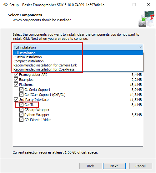
For detailed installation instructions, refer to the Installing the Framegrabber SDK topic of the Basler Product Documentation.
First Steps in microDisplay X#
-
For a first view of the images, open microDisplay X.
-
Configure some basic settings, which simplify image acquisition with the Basler racer 2 camera:
- Under Tools > Settings > Acquisition, set the Number of Buffers to
100. This enables you to browse through the acquired images, which is very useful for camera calibration. -
Set the Acquisition Timeout to a high value, e.g.,
1000 s. This is mandatory for setting up the trigger and avoids running into timeouts.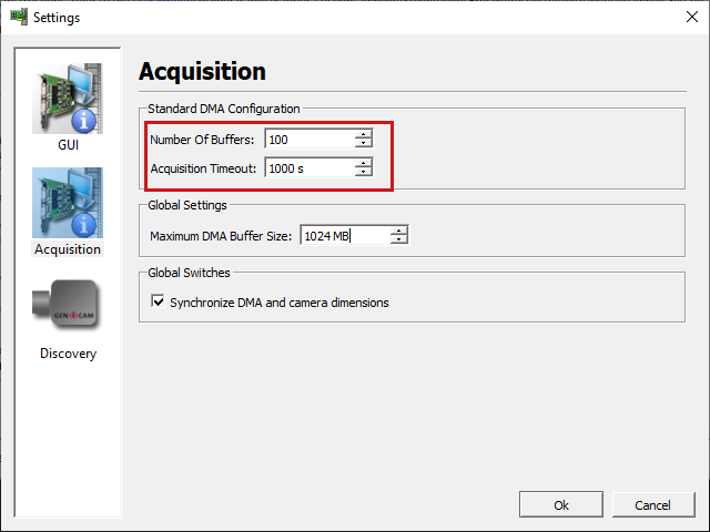
-
Under Tools > Settings > Discovery, select the Autoconnect discovered cameras check box.
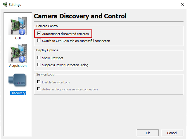
- Under Tools > Settings > Acquisition, set the Number of Buffers to
-
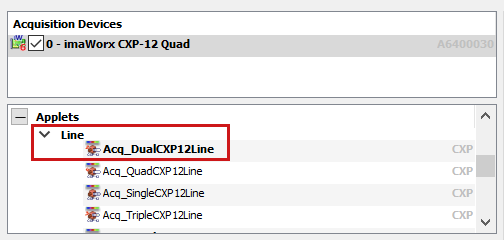
In microDisplay X, load an applet. See Possible Topologies to find out which applet is required for your setup.
-
Double-click the applet name. The frame grabber FPGA is now configured with your applet.
-
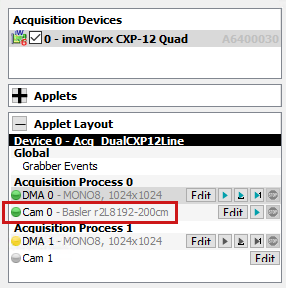
As you have selected Autoconnect discovered cameras, the camera should now be connected:
-
You can now switch between the parameters of camera and frame grabber or interface card by clicking DMA 0 or Cam 0 in the Applet Layout pane. If you have connected multiple cameras to one or multiple frame grabbers or interface cards, you can select the camera and DMA channel here.
- Configure the camera and frame grabber or interface card as desired.
-
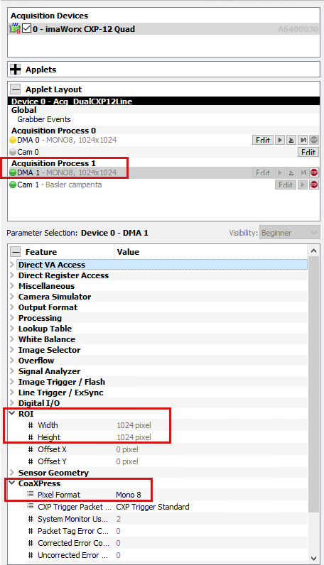
Important frame grabber or interface card parameters must match with the camera settings. These are:
- CoaXPress > Pixel Format
- ROI > Width
- For ROI > Height, define your desired image height. This parameter value defines the number of camera lines of the output image.
-
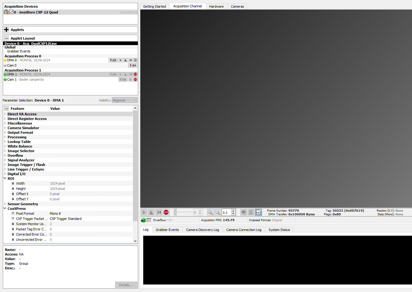
To start the image acquisition, switch to Acquisition Channel in the Viewing pane, and click the
 Play button.
 -
microDisplayX assists you in setting the frame grabber ROI. For line scan cameras, click Ignore.

You now see the camera images as long as the camera and the frame grabber or interface card are in free run mode.
Using CoaXPress Line Trigger#
To use a CoaXPress line trigger, set the camera to CoaXPress trigger mode and configure the camera and frame grabber or interface card as follows:
Stop Image Acquisition Before Configuring Parameters
Before configuring any parameter settings, you must stop the image acquisition. Otherwise, some parameters can't be edited.
- In the Applet Layout pane, select Cam 0.
-
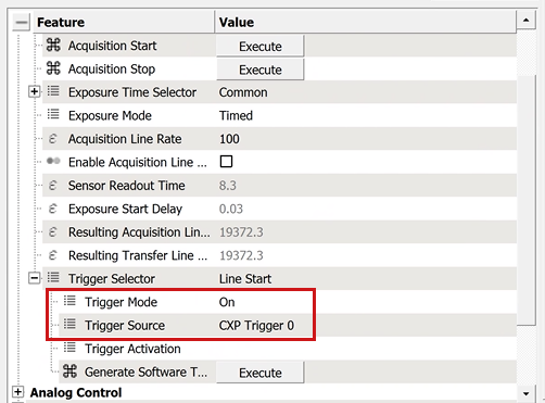
In the Parameter Selection pane under Acquisition Control, set the following parameters:
Trigger Mode=OnTrigger Source=Cxp Trigger 0
By default, the frame grabber uses an internal generator with a period of 200 µs. To change the source or to use the shaft encoder, select DMA 0 in the Applet Layout pane and configure the Line Trigger / ExSync parameters for your hardware setup: 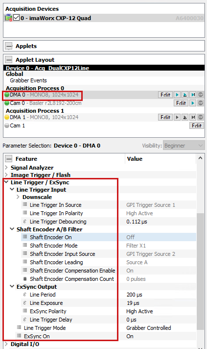
For a detailed explanation of the parameters, refer to the applet documentation for imaFlex CXP-12 Quad, imaWorx CXP-12 Quad and for the CXP-12 Interface Cards.
The Exposure Modes Trigger Width and Trigger Controlled#
To control the exposure time with external signals, you can use the two exposure modes Trigger Width and Trigger Controlled.
- Use
Trigger Widthif you connect your trigger signal directly to the IO of the camera. - Use
Trigger Controlledif CXP trigger packets are used and the triggers are coming via the camera.
Exposure Mode Trigger Width#
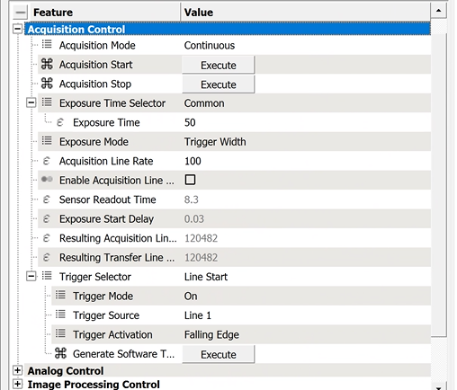
To use the exposure mode Trigger Width, you must set the following parameters in the camera:
- To switch to this exposure mode, set the camera parameter
Exposure Mode=Trigger Width. - To configure the trigger, set the following parameters:
Trigger Selector=Line StartTrigger Mode=OnTrigger Sourceto the IO to which you have connected your trigger to e.g.Line1.- If you have inverted signals, you can set optionally
Trigger Activation=Falling Edge.
In the exposure mode Trigger Width, the camera directly uses the trigger signals from the IO and not via CXP. Therefore, it isn't necessary to configure any trigger parameters for the frame grabber, if you select the exposure mode Trigger Width.
Exposure Mode Trigger Controlled#
To use the exposure mode Trigger Controlled, you must set the following parameters in the camera:
- To switch to this exposure mode, set the camera parameter
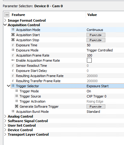
Exposure Mode=Trigger Controlled. -
To configure the trigger, set the following parameters. This starts and ends the exposure by a CoaXPress trigger:
Trigger Selector=Exposure StartTrigger Mode=OnTrigger Source=Cxp Trigger 0.
Trigger Selector=Exposure EndTrigger Mode=OnTrigger Source=Cxp Trigger 1.
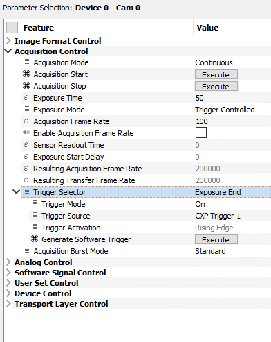
Now, you must configure the frame grabber to generate Cxp Trigger 0 and Cxp Trigger 1 trigger packets. You have the following three options:
- By default, an internal generator is used:
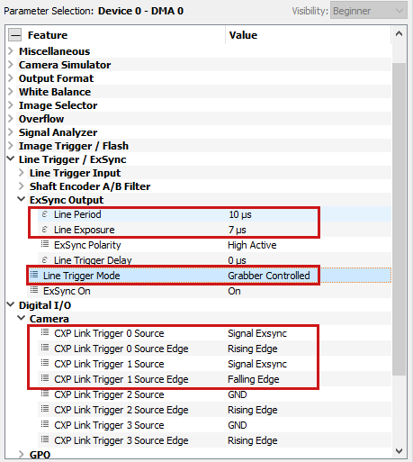
- If you change the
LineTriggerModeparameter toAsync Gated Trigger, you can use IO signals to control the exposure time: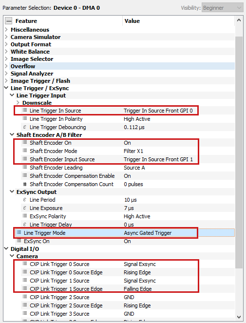
- Alternatively, you can bypass an IO signal directly to
CXP Link Trigger 0andCXP Link Trigger 1to control the start and end of the exposure: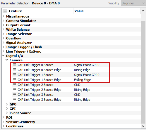
画像の検査#
microDisplay X offers several ways to examine the acquired images. The following items are helpful when you want to calibrate your camera:
- The Line Histogram view
- The Line Profile view
- Flipping through the acquired image sequence
- Getting the pixel values or zooming in for each pixel
- Saving the current image or an image sequence
For detailed information, refer to the Examining Images topic of the Basler Product Documentation.
Copying the SDK Code#
To copy the configuration into your SDK program, select Details of any parameter and copy the SDK code.
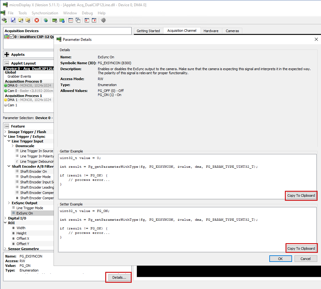
Alternatively, you can save a configuration file in microDisplay X and load it in your SDK program. For detailed information, refer to the Saving Applet Configuration topic of the Basler Product Documentation.
For GenTL usage, follow the same parameter configuration. You find the GenTL Producer in the %GENICAM_GENTL64_PATH% directory.