Encoder Control#
直交エンコーダーは、インクリメンタル、ロータリー、またはシャフトエンコーダーとも呼ばれます。通常、動きや位置の変化を測定する必要がある自動化アプリケーションで使用されます。
Encoder Control機能は、Basler racer 2カメラでのみ使用できます。
機能を使用する#
仕組み#
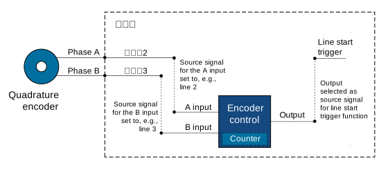
Encoder Controlは、ロータリーまたはリニアのいずれかで、2つの出力信号AおよびBを生成する直交エンコーダーに接続されます。これらは、位相またはソースAおよびBとも呼ばれます。これら2つの信号には90°の位相差があり、エンコーダーの前進および後退の方向を追跡するために使用されます。位相AおよびBは、カメラのEncoder Controlの入力信号になります。
次の画像は、Encoder Controlの一般的な実装を示しています。
Encoder Direction of Motion#
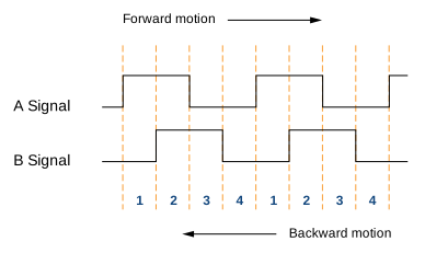
エンコーダーは、前進または後退のいずれかの方向に移動できます。動きの方向を検出するために、Encoder ControlはAおよびB信号の立ち上がりエッジと立ち下がりエッジの順序を読み取ります。
- 前進方向の動き: A信号がB信号より90°早く立ち上がります。位相の順序は1-2-3-4です。
- 後退方向の動き: B信号がA信号より早く立ち上がります。位相の順序は4-3-2-1です。
次の画像は、AおよびB信号のデジタル信号レベルに対応する4つの位相を示しています。
Position Counter#
Encoder Controlは、AおよびB信号によって駆動されるPosition Counterを使用します。カウンター値は、前進方向の動きでインクリメントされ、後退方向の動きでデクリメントされます。
Position Counterは継続的に実行されます。その値は、最後のクリア以降に受信された入力信号の数を示します。したがって、カウンター値は、前進または後退の動きの方向に関連するターゲットオブジェクトの現在位置を常に反映します。
Encoder Mode#
エンコーダーモードは、入力されたエンコーダー信号がEncoder Controlによってどのように計算されるかを制御します。
Four Phase Mode#
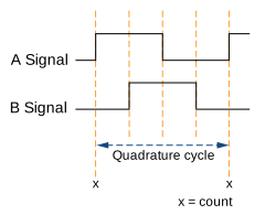
4つの完全に完了した信号位相が1つの直交サイクルを形成します。完全な直交サイクルごとに、つまりA信号のエッジが立ち上がるときに、直交エンコーダーカウンターが1ずつインクリメントまたはデクリメントされます。
Four Phaseモードは非常に堅牢であり、2つの位相間の少量の信号ジッターをフィルタリングして除外することができます。
High Resolution Mode#
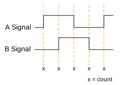
High Resolutionモードでは、サイクルあたりのカウントが4倍になります。エンコーダーカウンターは、各信号位相で、つまりA信号とB信号のエッジが立ち上がるときと立ち下がるときに1ずつインクリメントまたはデクリメントされます。
情報
High Resolutionモードではジッターフィルタリングは不可能です。したがって、High Resolutionモードは次のものと組み合わせて使用することはお勧めしません。 エンコーダー出力モード が次のように設定されている場合: Motion 2つの位相間のジッターにより、連続した出力トリガーパルスが発生する可能性があるためです。
Encoder Output Mode#
エンコーダー出力モードでは、Encoder Controlが有効な出力信号を生成するための条件を設定できます。次のエンコーダー出力モードを使用できます。
Motion: 動きの方向に関係なく、出力トリガー信号が生成されます。DirectionUp: すべての位置インクリメントで出力トリガー信号が生成されます。 前進 方向。逆方向の動きは無視されます。DirectionDown: すべての位置インクリメントで出力トリガー信号が生成されます。 backward 方向。順方向の動きは無視されます。PositionUp: 出力トリガー信号は、すべてで生成されます。 new の位置( 前進 方向)。エンコーダーが逆転した場合、逆転が始まった位置を再び通過するまで、出力トリガー信号は生成されません。PositionDown: 出力トリガー信号は、すべてで生成されます。 new の位置( backward 方向)。エンコーダーが逆転した場合、逆転が始まった位置を再び通過するまで、出力トリガー信号は生成されません。Off: 出力トリガー信号は生成されません。
追加パラメーター#
EncoderDivider: エンコーダー出力トリガー信号を生成するために必要な、エンコーダーからの入力信号の数を決定します。EncoderValue: Position Counterの現在の値を取得します。このPropertyは読み取り専用です。EncoderReset: Position Counterの現在のCounterの値を0にリセットします。これにより、Encoder Control全体がリセットされ、再起動されます。再起動直後から信号パルスのカウントが開始されます。
Encoder Control の設定#
Encoder Controlを設定するには:
- パラメーターを
EncoderSelectorパラメータをEncoder1. - パラメーターを
EncoderSourceAPropertyを利用可能なソース信号のいずれかに設定します(例:Line2. - パラメーターを
EncoderSourceBPropertyを利用可能なソース信号のいずれかに設定します(例:Line3. - パラメーターを
EncoderModeパラメーターを次のいずれかの値に設定します。 - パラメーターを
EncoderDividerPropertyを希望する入力信号数に設定します。 - パラメーターを
EncoderOutputModePropertyを有効にする output mode の種類に設定します(例:Motion.
エンコーダー信号によってカメラがトリガーされるように設定するには:
- パラメーターを
TriggerSelectorパラメータをLineStart. - パラメーターを
TriggerModeパラメータをOn. - パラメーターを
TriggerSourceパラメータをEncoder1.
サンプルコード#
// Select the desired encoder selector
camera.EncoderSelector.SetValue(EncoderSelector_Encoder1)
// Select line 2 as the source signal for the A input of the encoder control
camera.EncoderSourceA.SetValue(EncoderSourceA_Line2);
// Select line 3 as the source signal for the B input of the encoder control
camera.EncoderSourceB.SetValue(EncoderSourceB_Line3);
// Select the desired encoder mode
camera.EncoderMode.SetValue(EncoderMode_FourPhase);
// Determine the number of input signals needed to generate an encoder output trigger signal
camera.EncoderDivider.SetValue(1);
// Select the desired encoder output mode
camera.EncoderOutputMode.SetValue(EncoderOutputMode_Motion);
INodeMap& nodemap = camera.GetNodeMap();
// Select the desired encoder selector
CEnumParameter(nodemap, "EncoderSelector").SetValue("Encoder1");
// Select line 2 as the source signal for the A input of the encoder control
CEnumParameter(nodemap, "EncoderSourceA").SetValue("Line2");
// Select line 3 as the source signal for the B input of the encoder control
CEnumParameter(nodemap, "EncoderSourceB").SetValue("Line3");
// Select the desired encoder mode
CEnumParameter(nodemap, "EncoderMode").SetValue("FourPhase");
// Determine the number of input signals needed to generate an encoder output trigger signal
CIntegerParameter(nodemap, "EncoderDivider").SetValue(1);
// Select the desired encoder output mode
CEnumParameter(nodemap, "EncoderOutputMode").SetValue("Motion");
// Select the desired encoder selector
camera.Parameters[PLCamera.EncoderSelector].SetValue(PLCamera.EncoderSelector.Encoder1);
// Select line 2 as the source signal for the A input of the encoder control
camera.Parameters[PLCamera.EncoderSourceA].SetValue(PLCamera.EncoderSourceA.Line2);
// Select line 3 as the source signal for the B input of the encoder control
camera.Parameters[PLCamera.EncoderSourceB].SetValue(PLCamera.EncoderSourceB.Line3);
// Select the desired encoder mode
camera.Parameters[PLCamera.EncoderMode].SetValue(PLCamera.EncoderMode.FourPhase);
// Determine the number of input signals needed to generate an encoder output trigger signal
camera.Parameters[PLCamera.EncoderDivider].SetValue(1);
// Select the desired encoder output mode
camera.Parameters[PLCamera.EncoderOutputMode].SetValue(PLCamera.EncoderOutputMode.Motion);
/* Macro to check for errors */
#define CHECK(errc) if (GENAPI_E_OK != errc) printErrorAndExit(errc)
GENAPIC_RESULT errRes = GENAPI_E_OK;  /* Return value of pylon methods */
/* Select the desired encoder selector */
errRes = PylonDeviceFeatureFromString(hdev, "EncoderSelector", "Encoder1");
CHECK(errRes);
/* Select line 2 as the source signal for the A input of the encoder control */
errRes = PylonDeviceFeatureFromString(hdev, "EncoderSourceA", "Line2");
CHECK(errRes);
/* Select line 3 as the source signal for the B input of the encoder control */
errRes = PylonDeviceFeatureFromString(hdev, "EncoderSourceB", "Line3");
CHECK(errRes);
/* Select the desired encoder mode */
errRes = PylonDeviceFeatureFromString(hdev, "EncoderMode", "FourPhase");
CHECK(errRes);
/* Determine the number of input signals needed to generate an encoder output trigger signal */
errRes = PylonDeviceSetIntegerFeature(hdev, "EncoderDivider", 1);
CHECK(errRes);
/* Select the desired encoder output mode */
errRes = PylonDeviceFeatureFromString(hdev, "EncoderOutputMode", "Motion");
CHECK(errRes);
# Select the desired encoder selector
camera.EncoderSelector.Value = "Encoder1"
# Select line 2 as the source signal for the A input of the encoder control
camera.EncoderSourceA.Value = "Line2"
# Select line 3 as the source signal for the B input of the encoder control
camera.EncoderSourceB.Value = "Line3"
# Select the desired encoder mode
camera.EncoderMode.Value = "FourPhase"
# Determine the number of input signals needed to generate an encoder output trigger signal
camera.EncoderDivider.Value = 1
# Select the desired encoder output mode
camera.EncoderOutputMode.Value = "Motion"
pylon Viewerを使用して、パラメーターを簡単に設定することもできます。