Camera Calibration#
To use the camera as a measuring instrument, camera parameters such as focal length, lens distortion, and the relationship of the cameras to each other must be known exactly. The parameters are determined by calibration and are used for image rectification, which is the basis for all further image processing. The Stereo ace camera rectifies images automatically based on the camera's calibration.
The Stereo ace cameras are calibrated during production. Recalibration may be necessary if the Stereo ace camera has been exposed to strong mechanical forces, e.g., if it has been dropped. You can tell that recalibration is necessary if the camera suddenly doesn't deliver any 3D data anymore.
Self-Calibration#
The Stereo ace camera has a self-calibration mode that runs at a low frequency in the background. In this mode, the camera observes the alignment of lines in two rectified images. A mechanical impact, e.g., by dropping the camera, can lead to misalignment. If a significant misalignment is detected, it is corrected automatically.
To enable self-calibration, set the BslSelfCalibration parameter to On.
The value of the BslSelfCalibrationUpdateCounter parameter increases with each automatic correction. After a manual recalibration of the camera, it is reset to 0.
Under normal conditions, e.g., without mechanical impact on the Stereo ace camera, self-calibration should never occur. Self-calibration allows the Stereo ace camera to operate normally even after a misalignment has been detected as it is corrected automatically. However, Basler recommends recalibrating the camera manually if the BslSelfCalibrationUpdateCounter is not 0.
Manual Calibration#
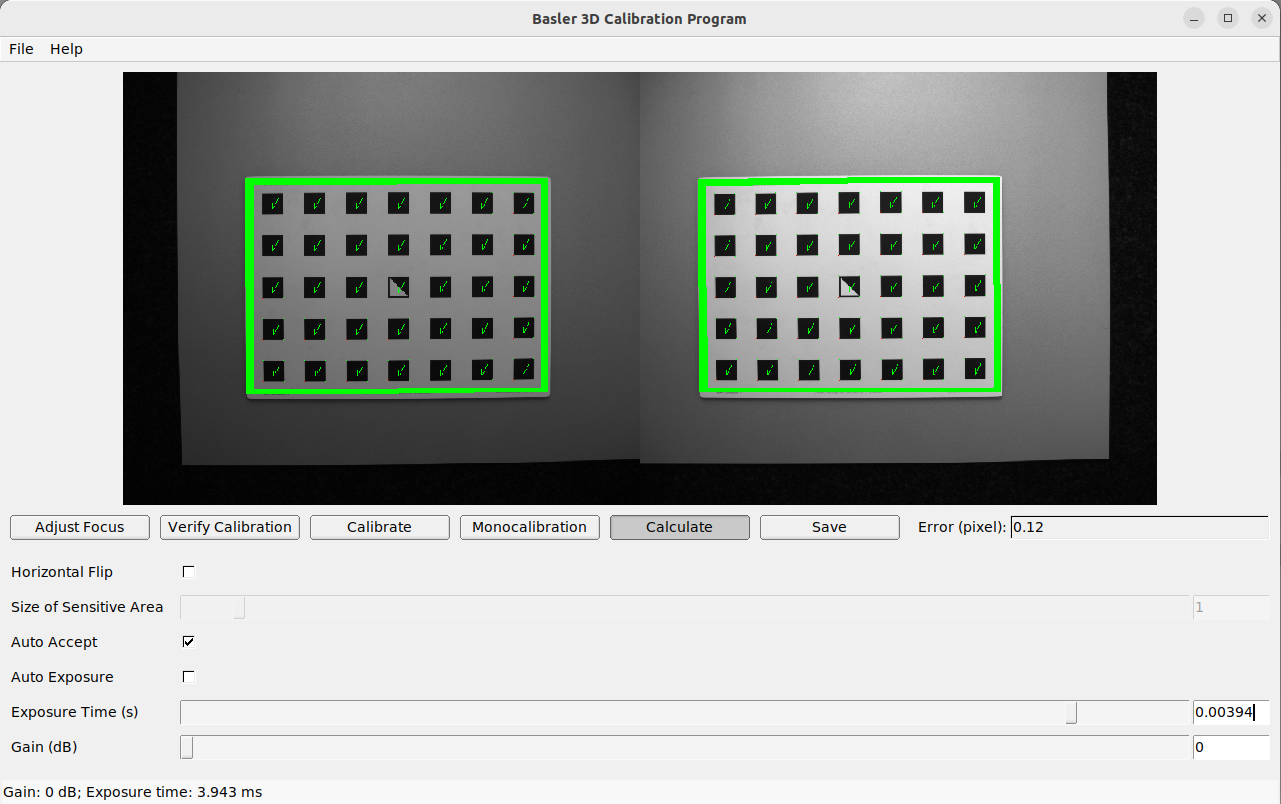
During manual calibration, the calibration grid must be detected in different poses. When holding the calibration grid, make sure that all black squares of the grid are completely visible and not occluded in both camera images. Correctly detected squares get a green check mark. All black squares must be detected correctly to ensure proper calibration. If some of the squares are not detected at all or only briefly, bad lighting conditions or a damaged grid may be the cause. Squares in overexposed parts of the calibration grid are highlighted in red. In this case, you must adjust the lighting conditions or exposure settings. A thick green border around the calibration grid indicates that it was detected correctly in both camera images.
Hold the calibration grid in front of the camera, making sure that all black squares of the grid are completely visible and not occluded in both camera images. Correctly detected squares get a green check mark. All black squares must be detected correctly to ensure proper calibration. If some of the squares are only visible briefly or are not detected at all, bad lighting conditions or a damaged grid may be the cause. Squares in overexposed parts of the calibration grid are highlighted in red. In this case, you must adjust the lighting conditions or exposure settings. A thick green border around the calibration grid indicates that it was detected correctly in both camera images.
Manual calibration can be carried out using the Stereo Calibration Tool. Start the tool from the Stereo Camera Viewer by clicking Tools > Stereo Calibration Tool. The tool has different tabs for the individual steps of the calibration. These are described in detail below:
- Initial settings
- Adjust Focus
- Verify Calibration
- Calibrate
- Monocalibration
- Calculate
- Save
初期設定#
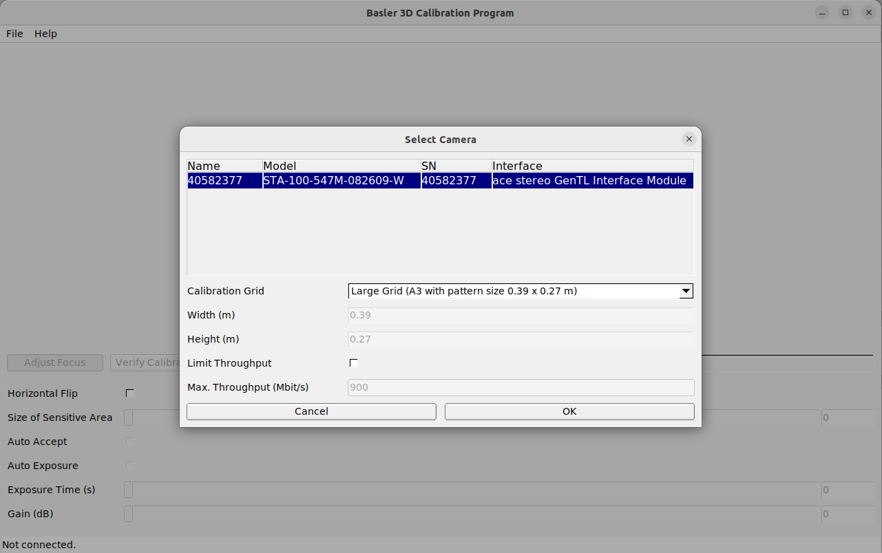
To start the calibration procedure, you have to select the camera and a calibration grid.
- In the Tools menu of the Stereo Camera Viewer, click Stereo Calibration Tool to start the tool.
- In the File menu of the Stereo Calibration Tool, click Connect Camera.
The Select Camera dialog opens. Available cameras are listed there automatically. - Select the desired camera.
- In the Calibration Grid drop-down list, select the desired calibration grid.
- OKをクリックします。
Verify Calibration#
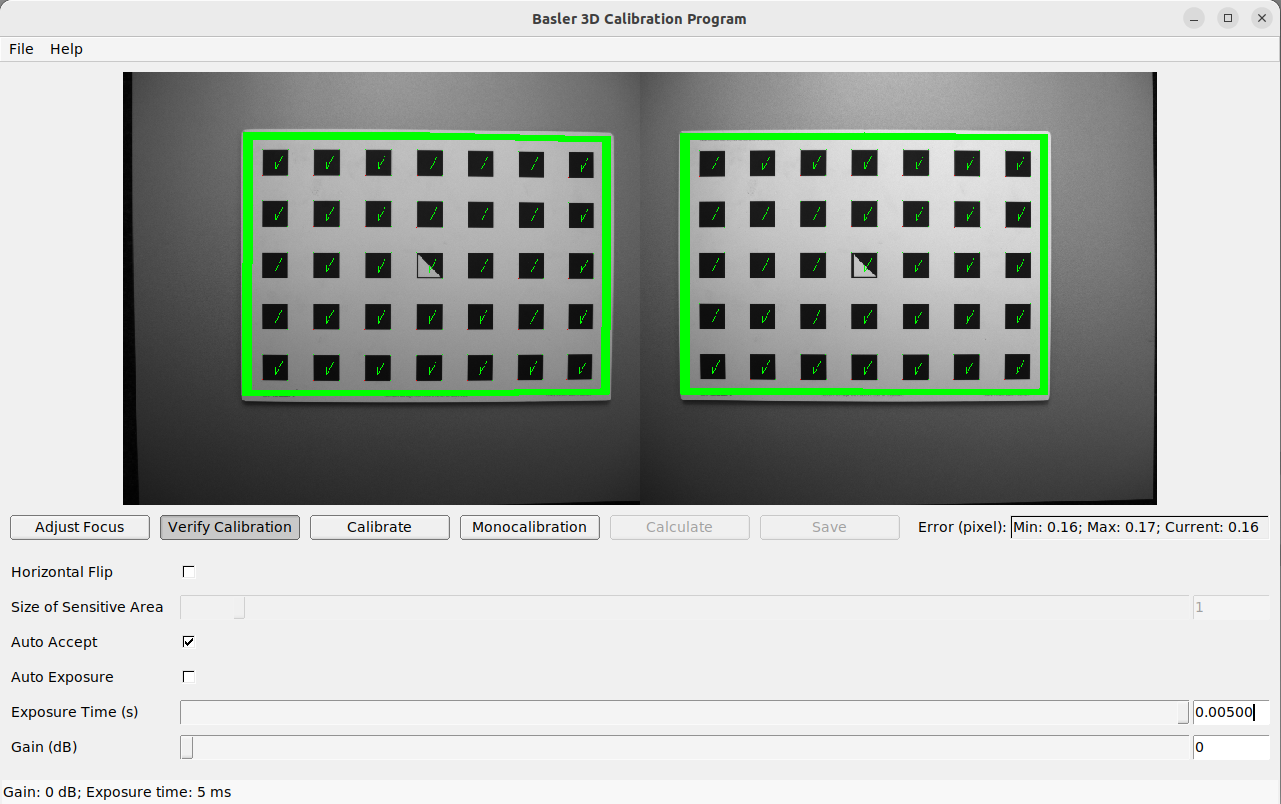
Now, you can verify the current calibration. The typical calibration error is below 0.2 pixels. If the error shown for your camera here is in this range, you can exit the calibration procedure. If the calibration error is greater, you should continue with the calibration procedure to ensure optimum camera performance.
To perform the verification, hold the grid in front of the cameras such that it is visible by both cameras at the same time. As soon as the grid is detected, the calibration error is computed automatically and the result is displayed on the screen.
If you want to go ahead with the calibration, click Calibrate.
情報
To compute a meaningful calibration error, the grid should be held as close as possible to the cameras. If the grid only covers a small section of the camera images, the calibration error will always be lower than if the grid covers the full image. For this reason, the minimum and maximum calibration errors during verification are shown in addition to the calibration error at the current grid position.
Calibrate#
Specify a suitable exposure time before starting the calibration. To achieve good calibration results, the images should be well-exposed and motion blur should be avoided. Therefore, the exposure time should be as short as possible while still allowing a good exposure of the scene.
Full calibration consists of calibrating each camera individually (monocalibration) performing stereo calibration to determine the relationship between the cameras. In most cases, the intrinsic calibration of each camera remains intact. Therefore, monocalibration is skipped by default during a recalibration but can be performed by clicking teh Monocalibration button.
During stereo calibration, both cameras are calibrated to each other to find their relative rotation and translation.
First, the grid should be held as close as possible to the camera and be kept very still. It must be fully visible in both images and the cameras should look perpendicularly onto the grid. If the grid is not perpendicular to the line of sight of the cameras, small green arrows pointing to the expected positions of the grid corners will indicate this.
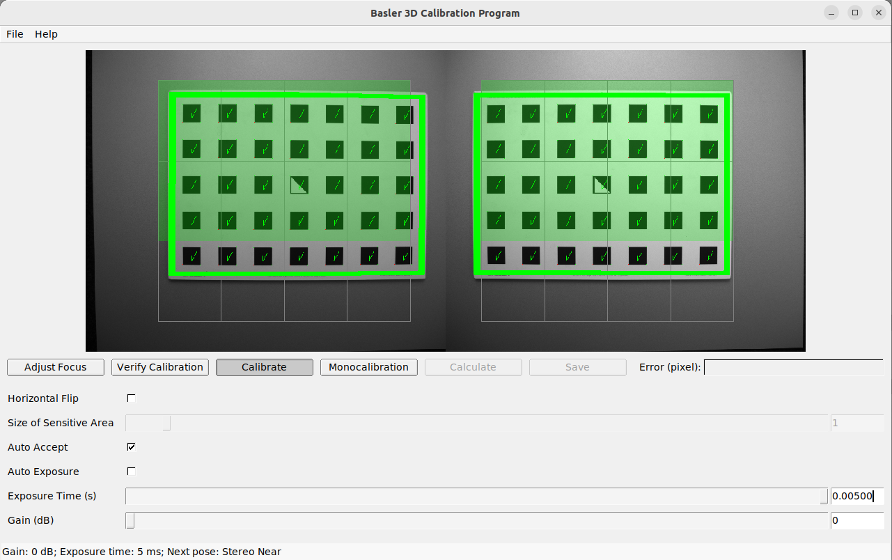
The grid must be kept very still. If motion blur occurs, the grid won't be detected. All grid cells that are drawn onto the image have to be covered by the calibration grid. This is visualized by filling the covered cells in green.
Once all grid cells are covered, they disappear and a single far cell is visualized. Now, the grid should be held as far away as possible from the cameras so that the small cell is covered. Arrows will indicate if the grid is still too close to the camera. When the grid has been detected successfully at the far pose, the cell is filled in green and the result can be computed.
If stereo calibration yields an unsatisfactory calibration error, you should perform monocalibration first and then repeat the stereo calibration.
Monocalibration#
Monocalibration is the intrinsic calibration of each camera individually. Since the intrinsic calibration normally remains intact, monocalibration only needs to be performed if the result of stereo calibration is unsatisfactory.
For monocalibration, the grid has to be held in front of the cameras in certain poses. Arrows at the corners of the grid point to the green areas indicate that all grid corners should be placed inside the green areas. The green areas are called sensitive areas. The Size of Sensitive Area slider can control their size to ease calibration. However, please be aware that increasing their size too much may result in slightly lower calibration accuracy.
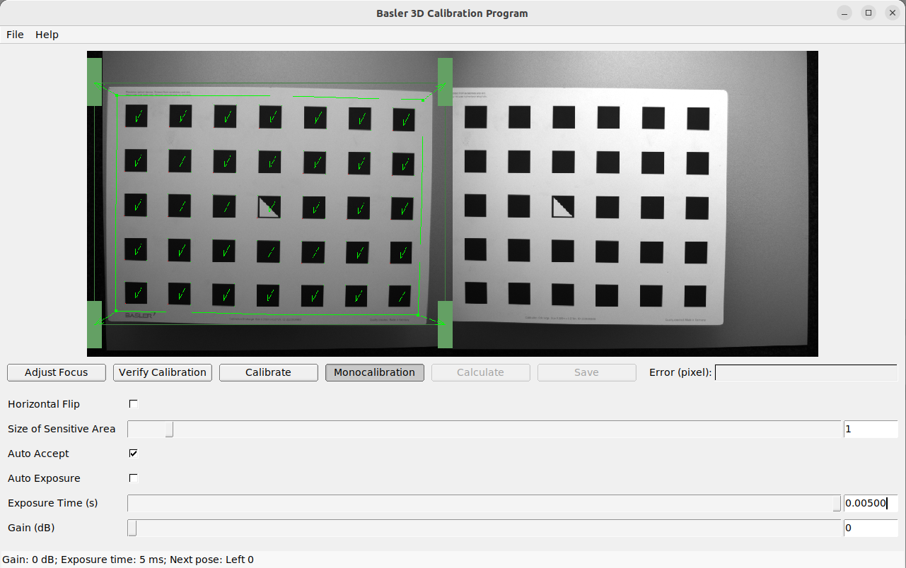
The monocalibration process involves five poses for each camera. After the corners or sides of the grid are placed on top of the sensitive areas, the process automatically shows the next pose required. When the process is finished for the left camera, the same procedure is repeated for the right one.
Calculate#
By clicking the Calculate button, the process is finished and the final result is displayed. The result indicated is the mean reprojection error of all calibration points. It's given in pixels and is usually a value below 0.2.
Save#
Click Save now to apply the calibration and save it to the Stereo ace device.