Grid Creator vTool#
To design the grid, you have to specify the number of rows and columns and the height and width of the individual cells. You can also configure whether you want the grid to cover the whole image or just a part of it. By default, the grid starts at the top left pixel of the image. By specifying an offset, you can place the grid where your region of interest begins.
Download the pylon Software Suite to use the Grid Creator vTool.
前提条件#
- The size of the images has to remain constant in your application. If image sizes vary, the grid may not fit anymore.
- Before you can configure the Grid Creator vTool, you have to connect its Image input pin to the Image output pin of another vTool.
Use Case Scenarios#
There are two different scenarios when using the Grid Creator depending on the region of interest (ROI):
- ROI covers the whole image.
- ROI only covers a part of the image.
The scenarios require different approaches when configuring the vTool.
ROI Covering the Whole Image#
This is the straightforward case. You take the source image, count the rows and columns, and enable the Auto Size Grid feature. This is a sample input image:
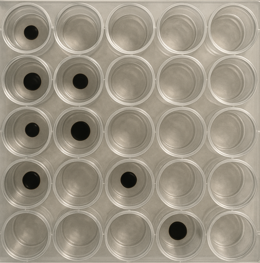
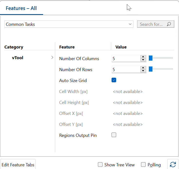
There are 5 columns and 5 rows. The necessary settings look like this:
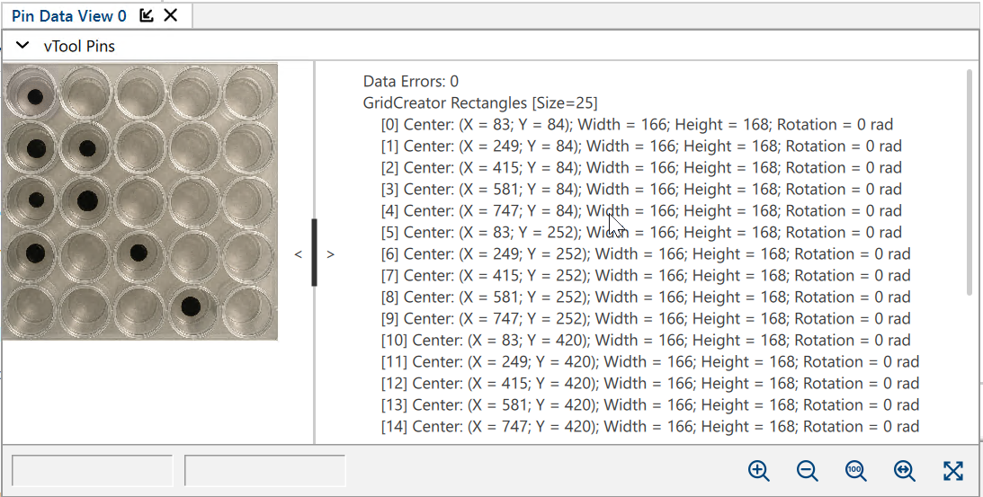
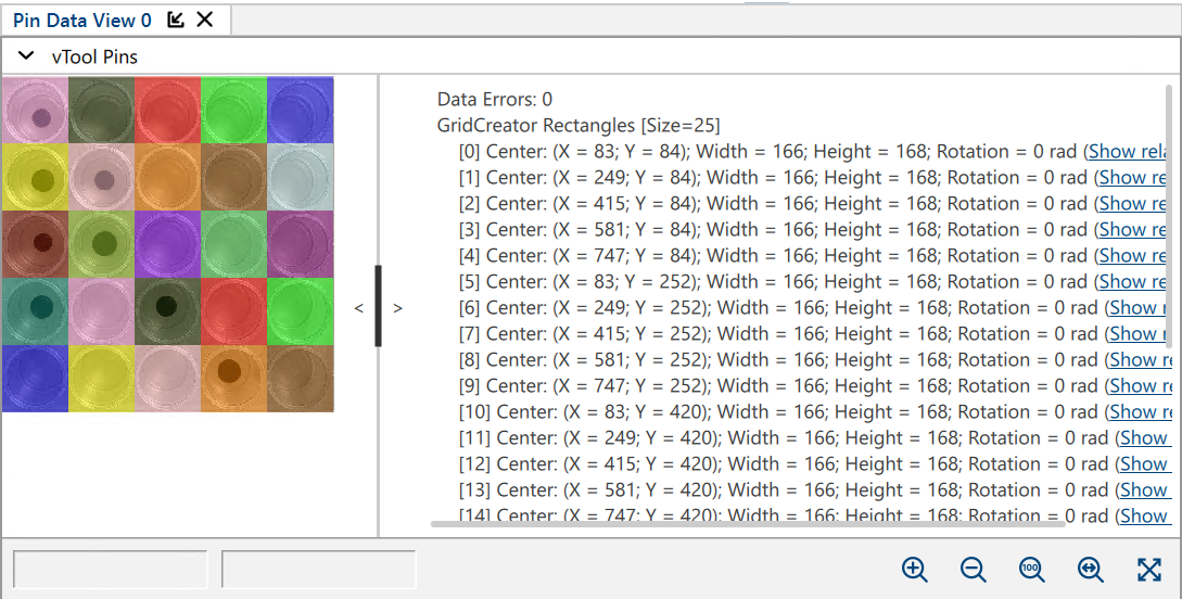
Open a pin data view and select the ImageLoading Image and GridCreator Rectangles pins. If you run the recipe now, you will see that 25 cells have been detected:
If you also enable the Regions outpin pin, a colored overlay shows the grid more clearly:
ROI Covering a Part of the Image#
This use case requires a few more steps. The sample image shows 30 AA batteries placed in a box. Some are pointing the wrong way round, i.e., bottom up. The spacing between them is irregular, and they don't fill the entire image.
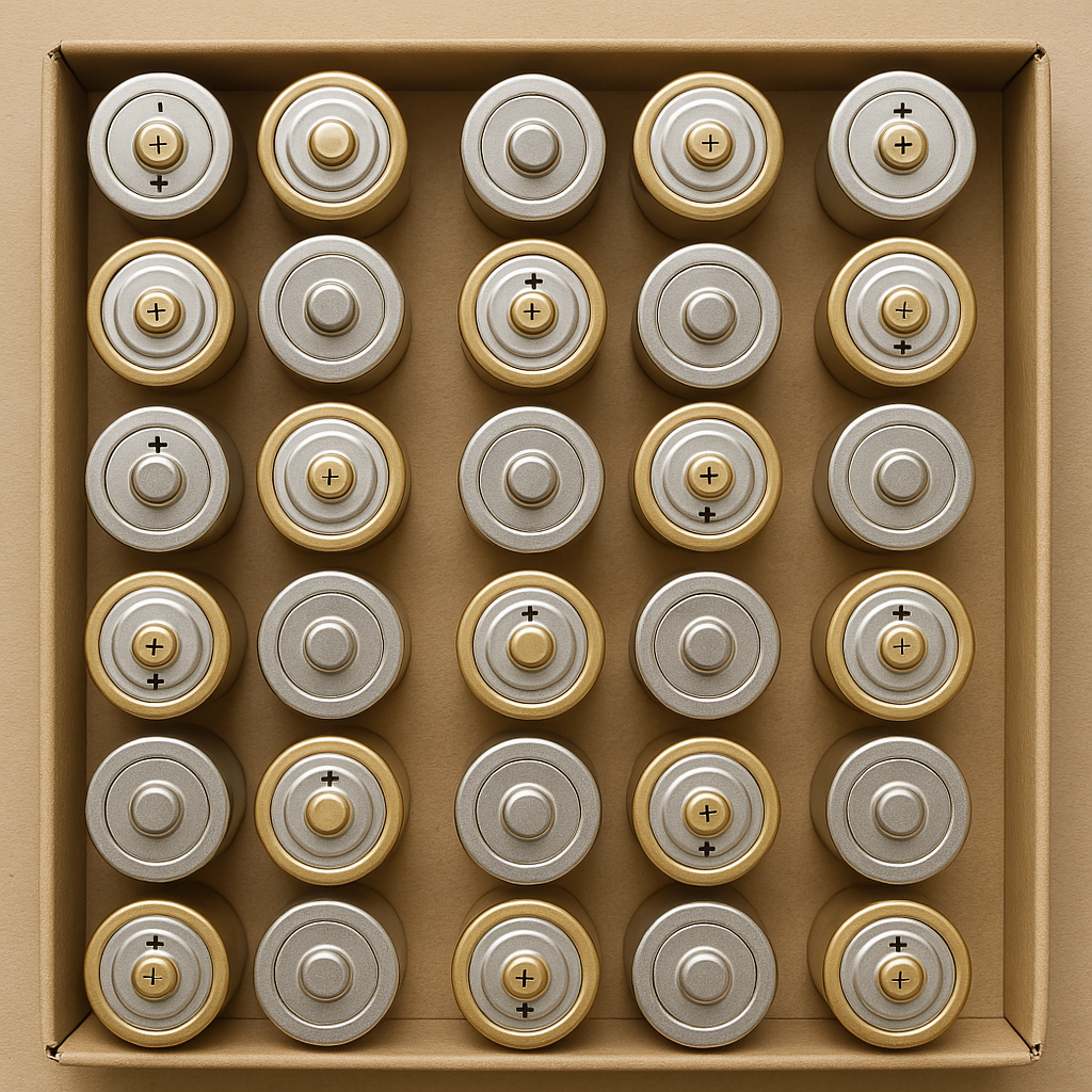
You start again by counting the columns and rows: 5 columns and 6 rows. If you enter these values and enable the Auto Size Grid feature, the result would look like this:
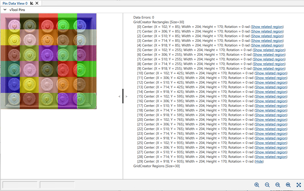
As you can see, a grid with 30 cells has been placed over the image. Because the margin hasn't been considered, however, not every cell contains exactly one battery. Especially in column 4, the result would be ambiguous as there are parts of two batteries visible in a cell.
To improve the grid layout, disable the Auto Size Grid feature. Instead, you have to manually specify cell width and height, i.e., the width and height of the batteries, as well as vertical and horizontal offsets, i.e, where you want the grid to start. By default, the grid's origin is in the top left corner (0,0).
By pointing your mouse at a pixel, you can view the pixel's coordinates in the status bar of the image window.
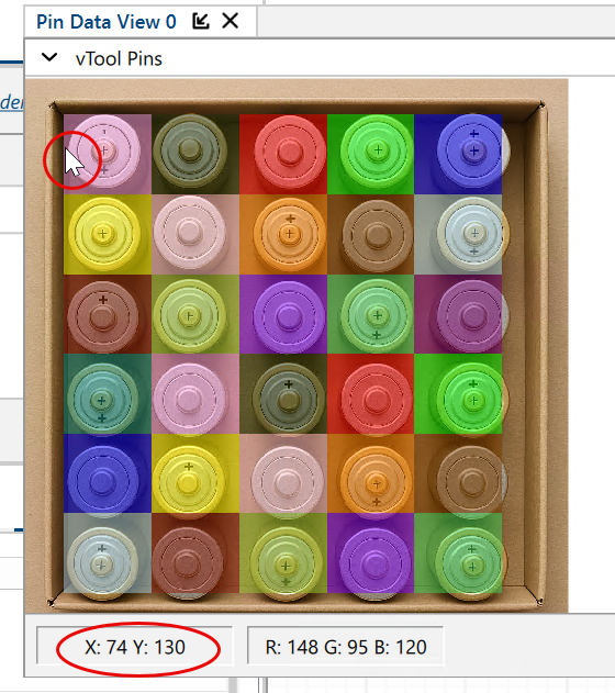
Using the pixel coordinates, you can determine the necessary properties of your grid and specify the corresponding parameter values.
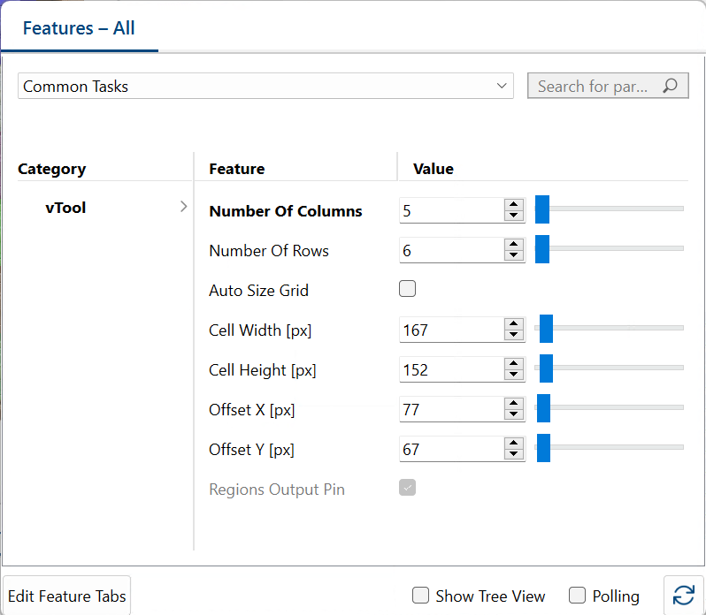
You can fine-tune width, height, and dimensions while the recipe is running until you are satisfied. The end result could look like this:
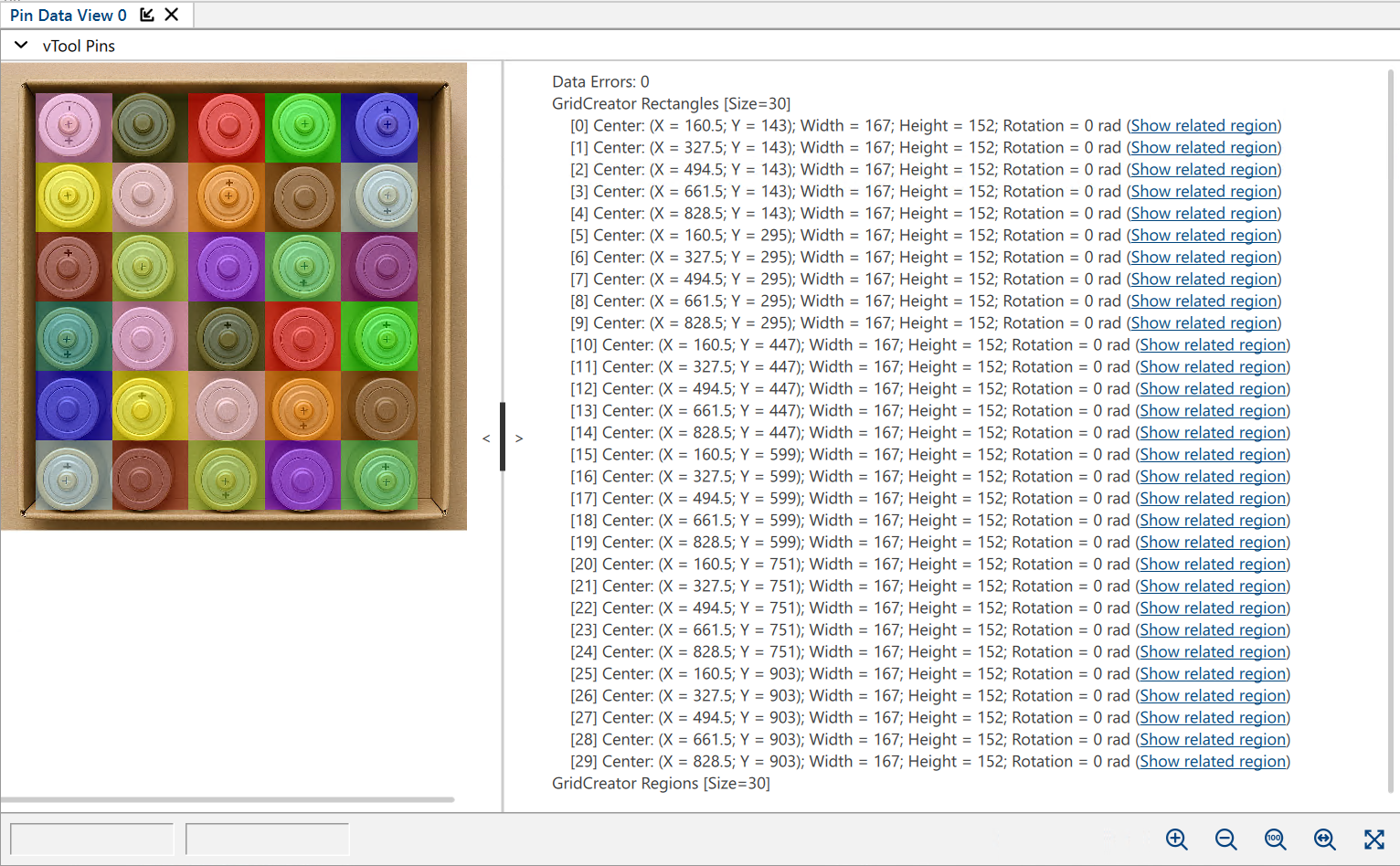
You can see that each battery is covered by a cell of the grid. All 30 batteries have been detected.
vToolの設定#
To configure the Grid Creator vTool, double-click it in the Workbench. A dialog opens showing all the available settings. Alternatively, you can find the same settings in the Features - All pane.
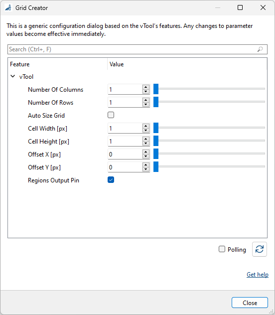
- Connect the Image input pin of the Grid Creator to the Image output pin of another vTool.
- Count the number of columns and rows in your image and enter the values in the Number of Columns and Number of Rows input fields accordingly.
- If you want your grid to cover the entire image, select the Auto Size Grid parameter.
This allows the vTool to divide the image into cells based on the number of columns and rows you have specified. If you need a smaller grid, continue with the next step. - Disable the Auto Size Grid parameter.
- Determine the width and height of the individual cells and enter the values in the Cell Width and Cell Height parameters accordingly.
See tip below. - Specify a horizontal and vertical offset.
ヒント
If you enable the Regions output pin, an overlay is displayed over the input image showing the different regions, i.e., cells. This allows you to immediately see the effects of your configuration in the pin data view while the recipe is running. To do this:
- Select the Regions Output Pin parameter.
- Open a pin data view and select the Image pin of the image source vTool and the Regions pin of the Grid Creator.
- Start the recipe.
You may have to play around with the settings a little to make the grid fit. If you hover with your mouse over a pixel in the image, the status bar of the pin data view shows you the coordinates of that pixel (X/Y). This should help you to find the right settings.
入力#
画像#
Accepts images directly from a Camera vTool or any other vTool that outputs images.
- データ型:Image
- Image format: 8-bit and 16-bit mono or color images (see Supported Pixel Formats)
出力#
Rectangles#
Returns a rectangle for each cell of the grid.
- データ型:RectangleF Array
領域#
Returns the number of regions in the grid and visualizes the regions in the image.
- データ型:Region Array
サポートされているPixel Format#
The following pixel formats are supported natively:
- Mono 8
- Mono 16
- Bayer XX 8
- Bayer XX 16
- RGB 8
- BGR 8