imaFlex CXP-12 Penta#
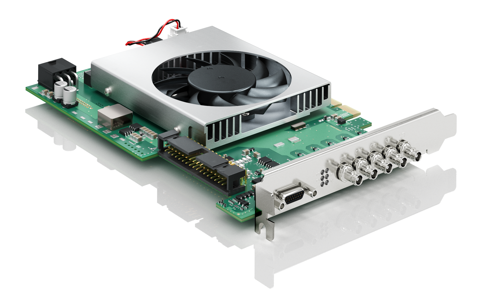
imaFlex CXP-12 Pentaをホストコンピュータにインストールするには、PCIe Gen. 3.0 x8スロット以上に差し込みます。次の画像は、5台のカメラが接続されたimaFlex CXP-12 Pentaを示しています。
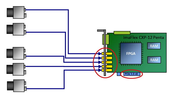
画像処理#
このフレームグラバーは VisualAppletsによって完全にプログラム可能です。特定のニーズに合わせて独自の画像処理アプリケーションを設計できます。Basler では、コンサルティングサポートや VisualApplets トレーニングを提供しているほか、お客様の特定のアプリケーションを Basler が実装することも可能です。
独自のアプレットの作成方法については、VisualApplets documentationを参照してください。
生産ラインへの統合#
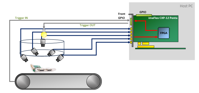
生産ラインへの統合のために、imaFlex CXP-12 Pentaには複数の汎用入出力が用意されています。使用するハードウェアアドオンに応じて、GPIOのうち8個(TTL Triggerボードを使用する場合)または24個(Opto-Coupled Trigger 5ボードを使用する場合)がガルバニック絶縁されています。
これらの GPIO により、次のことが可能になります。
- トリガー信号(照明信号やカメラ信号など)を送信して周辺機器を制御する
- 周辺機器(ロータリーエンコーダや光電センサなど)からさまざまなトリガー信号を受信する
- 複数のimaFlex CXP-12 Pentaフレームグラバーを同期する、および/または
- 接続されたデバイスを同期させます。
ソフトウェアプログラミングおよび設定インターフェース#
imaFlex CXP-12 Pentaには使いやすいAPIが用意されています。Framegrabber APIを使用すると、フレームグラバーをあらゆる画像処理アプリケーションに統合できます。Framegrabber APIを使用して、次の言語でコードを記述できます。
- C/C++
- C#(ラッパー利用可能)
- Python(ラッパー利用可能)
Framegrabber APIの詳細については、Framegrabber API documentationを参照してください。
また、BaslerのGenTL Interfaceを使用して、GenTLコンシューマーの形式でアプリケーションを開発することもできます。Basler GenTL Interfaceの詳細については、GenTL Interfaceドキュメントを参照してください。
コネクタとLED#
コネクター#
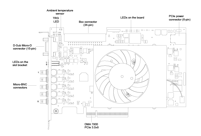
imaFlex CXP-12 Pentaには、次のコネクタがあります。
スロットブラケットのLED#
imaFlex CXP-12 Pentaのスロットブラケットには、個々のCXPリンクの状態を示す5つのLEDがあります。
 CXPリンクでの接続の準備が完了
 CXPリンクでの接続なし
ボード上のLED#
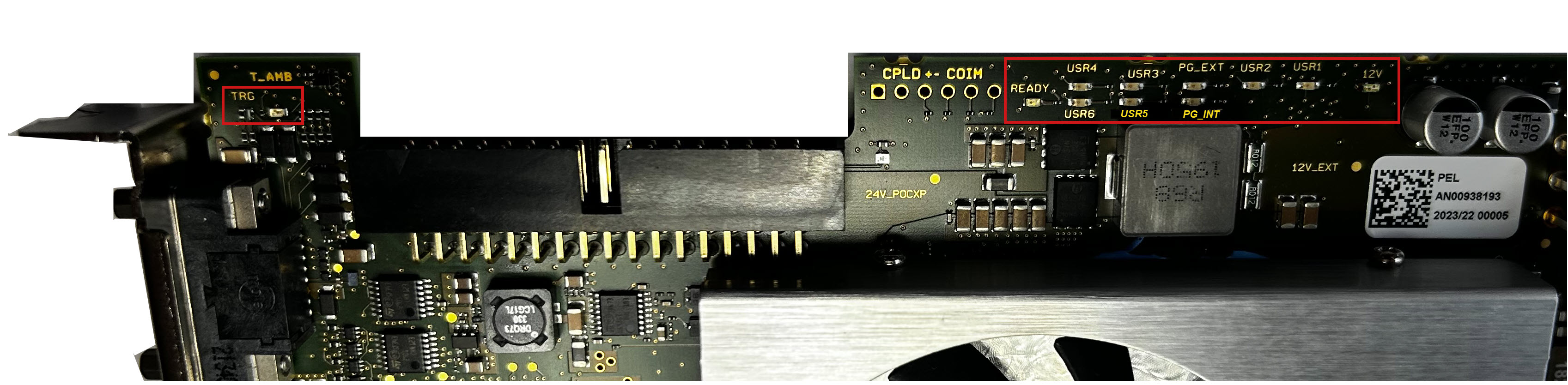
| LED名 | LEDの色 | 意味 |
|---|---|---|
| TRG | イエロー | 15ピンコネクタを介して供給される外部電圧。 |
| READY | オレンジ色 | FPGAは正常にコンフィグレーションされ、動作可能な状態です。 |
| PG_INT | 緑 | PG_INT = Power Good Internal PCIeスロットの電圧が安定しています。内部で生成された電圧も安定しています。 |
| PG_EXT | 緑 | 未定義/内部機能。 |
| USR1~USR6 | 緑 | ユーザー定義。LEDはVisualAppletsソフトウェアで制御できます。カメラのコネクタとは無関係であり、任意の目的に使用できます。 |
| 12V | 緑または赤 | オフ:フレームグラバーの電源が入っていません。 赤:フレームグラバーはPCIeスロット(12 VDC IN)のみから電源を受信しています。 緑:フレームグラバーの6ピン(12V)電源コネクタが、ホストコンピュータ経由で電源に接続されています。 |
仕様#
| imaFlex CXP-12 Penta | |
|---|---|
| ホストインターフェース | PCIe Gen 3 x8 (ダイレクトメモリーアクセス) |
| 帯域幅 (標準/最大) | 6520 MB/s |
| オンボードMemory | 2.5 GB DDR4-RAM |
| 電源 (入力) / 現在のPCIeスロット | 12 V (±5 %) / <1.5 A (actual values depend on processing) |
| 電源 (入力) / 現在のPCIe 6ピンコネクター | 12 V (±5 %) / <6.5 A (actual values depend on connected PoCXP cameras) |
| PoCXP電源 (出力) | CoaXPressコネクタあたり17 W(24 V DCレギュレート電源) |
| サイズ (L x H) | PCIe標準ハイト ハーフレングスカード: 167.64 mm x 111.15 mm |
| 重量 | 270 g |
| カメラインターフェース | 5 x CXP-12(CXP-1〜CXP-12、micro-BNC/HD-BNCコネクタ) |
| 周囲温度 | 50 °C コンピュータ内の適切なエアフローが推奨されます。 |
| 動作温度 | 0~50 °C(100 LFM時)a |
| 保管温度 | -50~80 °C |
| 動作時湿度 | 5~90 % |
| 保管時湿度 | 5~95 % |
| コンプライアンス | CE、FCC、RoHS、WEEE、REACH、UKCA、KC インターフェイスカードの証明書 詳細については、Baslerウェブサイトのコンプライアンスセクションを参照してください。 |
-
LFM = Linear Feet per Minute(風速の測定単位)。 ↩
情報
PCIeバスのデータスループットは、ホストコンピュータのマザーボード、チップセット、およびBIOS設定によって異なります。また、インストールされているPCIeボードの数もスループットに影響します。たとえば、PCIe x8コネクタがx4のパフォーマンスしかサポートしない場合があります。確実に確認するために、マザーボードのマニュアルを必ず隅々まで確認してください。
フロントGPIOコネクタ#
フロントGPIOコネクタは、フレームグラバーの基本的なトリガー設定をカバーしています。トリガーコネクタを使用することで、周辺機器(PLC)を制御できます。
ソケットはスロットブラケットに直接配置されています。
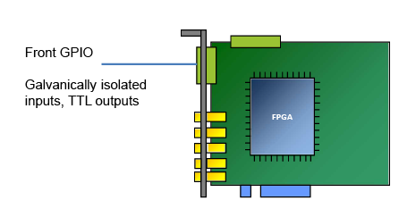
デフォルト設定では、フロントGPIOコネクタのトリガーコネクタは以下を提供します。
- 3つの差動入力信号、またはプルアップモードでの2つの差動および1つのシングルエンド入力信号
- 4つのTTL出力信号
情報
フロントGPIOコネクタのピン割り当てを設定して、以下のような異なる入力信号を提供できます。
- プルダウン
- 4つのシングルエンド信号(差動信号なし)。
GPIO設定を変更するには、Framegrabber SDKと一緒にインストールされたコマンドラインツールを使用します。
詳細については、入力設定およびgpioToolを使用したトリガー信号の物理プロパティの設定を参照してください。
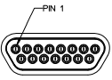
フロントGPIOコネクタのピンレイアウト#
情報
フロントGPIOコネクタは、MOLEX 83612-9020コネクタの形式で提供されます。このコネクタには、適合する既製の中継用MOLEX D-Subケーブル(MOLEX 083422-9018)が用意されています。
| ピン番号(3P FPGA) | 絶縁型 | 信号 | 基準信号 |
|---|---|---|---|
| 1 | はい | GPO 0 (TTL) | 5 V / GPIO GND(ピン6および15) |
| 2 | はい | GPO 1 (TTL) | 5 V / GPIO GND(ピン6および15) |
| 3 | はい | GPO 2 (TTL) | 5 V / GPIO GND(ピン6および15) |
| 4 | はい | GPO 3 (TTL) | 5 V / GPIO GND(ピン6および15) |
| 5 | いいえ | 5 V_OUT(絶縁型5V出力、最大500mA) | GPIO GND(ピン6および15) |
| 6 | いいえ | GPIO GND(絶縁型GND) | |
| 7 | いいえ | —(未接続) | |
| 8 | はい | GPI 2(差動信号に使用する場合はGPI2+) | GPI voltage IN(ピン10) / GPIO GND(ピン6および15) |
| 9 | はい | GPI 3(差動信号に使用する場合はGPI2-) | GPI voltage IN(ピン10) / GPIO GND(ピン6および15) |
| 10 | はい | GPI voltage IN(プルアップ/コンパレータ用4.5~28 V入力。VIN_REFはVINの20%) | GPIO GND(ピン6および15) |
| 11 | はい | GPI 0+ | GPI voltage IN(ピン10) / GPIO GND(ピン6および15) |
| 12 | はい | GPI 0- | GPI voltage IN(ピン10) / GPIO GND(ピン6および15) |
| 13 | はい | GPI 1+ | GPI voltage IN(ピン10) / GPIO GND(ピン6および15) |
| 14 | はい | GPI 1- | GPI voltage IN(ピン10) / GPIO GND(ピン6および15) |
| 15 | はい | GPIO GND (isolated GND) | |
| シールド | いいえ | GND (Non-isolated ground / Earth / bracket) |
可能なトポロジ#
imaFlex CXP-12 Pentaには、1、2、または4つのCXPチャンネルを持つカメラを接続するための多くの方法があります。すべてのカメラで使用されるCXPチャンネルの合計最大数は5つのCXP-12チャンネルです。各カメラは異なるCXPビットレートで動作できます。すべてのCXP 2.0ビットレートが、各CXPカメラで個別にサポートされています。
imaFlex CXP-12 Pentaは次のように操作できます。
| トポロジー | カメラの数 | チャンネル数 | トポロジー |
|---|---|---|---|
| One camera one channel single | 1 | 1 | 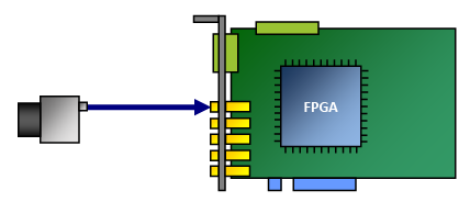 |
| One camera two channels single | 1 | 2 | 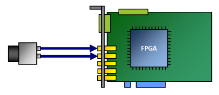 |
| One camera four channels single | 1 | 4 | 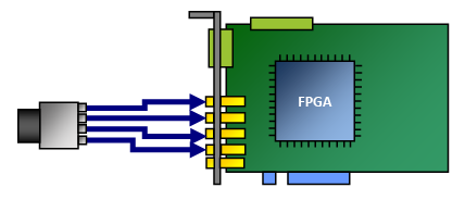 |
| Two cameras one channel each penta | 2 | 2 | 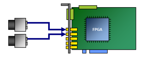 |
| Three cameras one channel each penta | 3 | 3 | 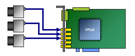 |
| Four cameras one channel each penta | 4 | 4 | 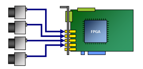 |
| Five cameras one channel each penta | 5 | 1 | 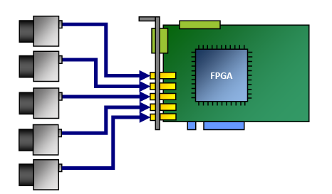 |
常に12 Vを供給するPCIe 6ピンコネクタを介してコンピュータの電源に接続されている場合、imaFlex CXP-12 PentaはPower over CXP(PoCXP)をサポートします。
カメラはどのような順序でも接続できます。接続トポロジーはポート番号に完全に依存しません。どのカメラチャンネルも、フレームグラバーのどのCXPポートにも接続できます。CXP 2.0トポロジー検出により、カメラとVisualAppletsアプレットの設定に応じて、ソフトウェア内でチャンネルが仮想的に再順序付けされます。
情報
1つのホストコンピュータで複数のimaFlex CXP-12 Pentaボードを使用する場合は、ホストコンピュータにボードごとにPCIe Gen. 3.0 x8以上のスロットが1つずつ利用できることを確認してください。詳細については、次のトピックを参照してください。
取得アプレット#
システムリソースの最適な使用を確保するため、imaFlex CXP-12 Penta用に設計されたすべての画像取り込みおよび処理機能が同時にimaFlex CXP-12 Pentaにロードされるわけではありません。
その代わりに、Baslerでは特定のアプリケーション分野の要件を満たすように組み合わせられた、特定の画像取得および処理機能のさまざまなコンパイルを提供しています。
通常、アプレットは特定のカメラインターフェース規格とトポロジ、特定の画像取得機能、および場合によっては特定の画像(前)処理機能をサポートします。
アプレットには、常にBaslerから提供される取得アプレット(Acquisition Applets)(*.dll)と、ユーザー自身またはBaslerによって VisualApplets で開発されたカスタムアプレット(*.hap)の2種類があります。
- 配信される Acquisition Applets の詳細については、Acquisition Applets for imaFlex CXP-12 Pentaを参照してください。
- 配信される Acquisition Applets (GenTLおよびFglib) のPDFマニュアルについては、Applets for imaFlex CXP-12 Penta Documentationを参照してください。
- imaFlex CXP-12 Pentaには標準でAcquisition Appletsが付属していますが、特定のアプリケーションで必要とされる高度な画像処理タスクを実行できるようにプログラミングすることも可能です。プログラミングは、Basler、認定パートナー、または使いやすいグラフィカルなFPGAプログラミング環境であるVisualAppletsを使用してご自身で行うことができます。
注意事項#
→ Safety Instructions (Frame Grabbers)を参照してください。
インストール#
→ Connecting Frame Grabbersを参照してください。
→ Connecting Camerasを参照してください。