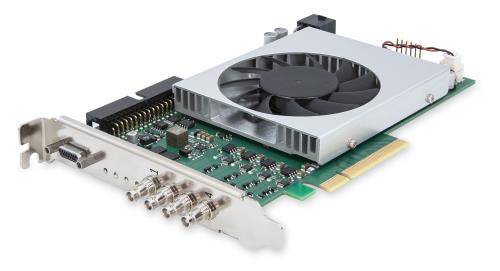
imaWorx CXP-12 Quad#
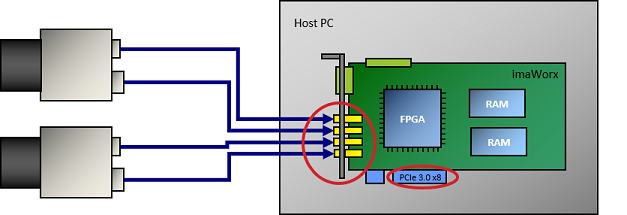
imaWorx CXP-12 Quadをコンピュータに取り付けるには、PCIe Gen. 3.0 x8以上のスロットに差し込みます。次の画像は、2台のカメラが接続されたimaWorx CXP-12 Quadを示しています。
画像処理#
画像処理機能は、ご要望に応じて利用可能です。ご興味のある方は、Baslerサポートまでお問い合わせください。
生産ラインへの統合#
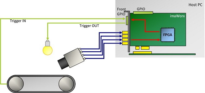
生産ラインへの統合のために、imaWorx CXP-12 Quadには複数の汎用入出力(GPIO)が備わっています。GPIOのうち4〜20個(使用するハードウェアアドオンによる)はガルバニック絶縁されています。
これらの GPIO により、次のことが可能になります。
- 照明信号やカメラ信号などのトリガー信号を送信して、周辺機器を制御します。
- ロータリーエンコーダや光電センサなど、周辺機器からさまざまなトリガー信号を受信します。
- 複数のimaWorx CXP-12 Quadフレームグラバーを同期させます。
- 接続されたデバイスを同期させます。
ソフトウェアプログラミングおよび設定インターフェース#
imaWorx CXP-12 Quadは、使いやすいAPIを提供します。Framegrabber APIを使用することで、フレームグラバーをあらゆる画像処理アプリケーションに統合できます。Framegrabber APIを使用して、次の言語でコードを記述できます。
- C/C++
- C#(ラッパー利用可能)
- Python(ラッパー利用可能)
Framegrabber APIの詳細については、Framegrabber API documentationを参照してください。
また、BaslerのGenTL Interfaceを使用して、GenTLコンシューマーの形式でアプリケーションを開発することもできます。Basler GenTL Interfaceの詳細については、GenTL Interfaceドキュメントを参照してください。
コネクタとLED#
コネクター#
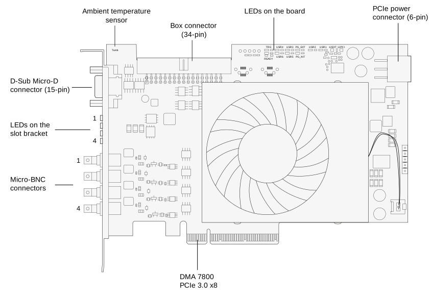
imaWorx CXP-12 Quadには、次のコネクタがあります。
スロットブラケットのLED#
imaWorx CXP-12 Quadのスロットブラケットには、個々のCXPリンクの状態を示す4つのLEDがあります。
 CXPリンクでの接続の準備が完了
 CXPリンクでの接続なし
ボード上のLED#
| LED名 | LEDの色 | 意味 |
|---|---|---|
| TRG | イエロー | 15ピンコネクタを介して供給される外部電圧。 |
| READY | オレンジ色 | FPGAは正常にコンフィグレーションされ、動作可能な状態です。 |
| PGINT | 緑 | PGINT = Power Good Internal PCIeスロットの電圧が安定しています。内部で生成された電圧も安定しています。 |
| PGEXT | 緑 | 未定義/内部機能。 |
| USR1~USR6 | 緑 | ユーザー定義。LEDはソフトウェアで制御できます。カメラコネクタとは関連付けられておらず、任意の目的に使用できます。 |
| 12EXT | 緑 | フレームグラバーのPCIe電源コネクターは、ホストコンピューター経由で電源に接続されています。 |
| 12PCI | 緑または赤 | 緑:フレームグラバーがPCIeスロット(12 VDC IN)から電力を受けています。 赤:フレームグラバーがPCIeスロットから電力を受けていません。 |
仕様#
| imaWorx CXP-12 Quad | |
|---|---|
| 注文番号 | 2200000482 |
| ホストインターフェース | PCIe Gen 3 x8 (ダイレクトメモリーアクセス) |
| 帯域幅 (標準/最大) | 6520 MB/s |
| オンボードMemory | 1.5GB DDR4-RAM |
| 電源 (入力) / 現在のPCIeスロット | 12 VDC (±5 %) / <1.5 A (actual values depend on processing) |
| 電源 (入力) / 現在のPCIe 6ピンコネクター | 12 VDC (±5 %) / <6.5 A (actual values depend on connected PoCXP cameras) |
| PoCXP電源 (出力) | 各CoaXPressコネクターにつき24 VDC安定化電源17 W |
| サイズ (L x H) | PCIe標準ハイト ハーフレングスカード: 167.64 mm x 111.15 mm |
| 重量 | 274 g |
| カメラインターフェース | 4 x CXP-12(CXP-1~CXP-12、マイクロBNC/HD-BNCコネクター) |
| 動作温度 | 0~50 °C(100 LFM時)a |
| 保管温度 | -50~80 °C |
| 動作時湿度 | 5~90 % |
| 保管時湿度 | 5~95 % |
| コンプライアンス | CE、FCC、RoHS、WEEE、REACH、UKCA、KC インターフェイスカードの証明書 詳細については、Baslerウェブサイトのコンプライアンスセクションを参照してください。 |
-
LFM = Linear Feet per Minute(風速の測定単位)。 ↩
情報
PCIeバスのデータスループットは、ホストコンピュータのマザーボード、チップセット、およびBIOS設定によって異なります。また、インストールされているPCIeボードの数もスループットに影響します。たとえば、PCIe x8コネクタがx4のパフォーマンスしかサポートしない場合があります。確実に確認するために、マザーボードのマニュアルを必ず隅々まで確認してください。
フロントGPIOコネクタ#
フロントGPIOコネクタは、フレームグラバーの基本的なトリガー設定をカバーしています。トリガーコネクタを使用することで、周辺機器(PLC)を制御できます。
ソケットはスロットブラケットに直接配置されています。
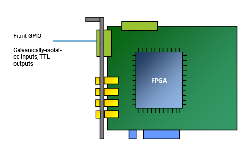
デフォルト設定では、フロントGPIOコネクタのトリガーコネクタは以下を提供します。
- 3つの差動入力信号、またはプルアップモードでの2つの差動および1つのシングルエンド入力信号
- 2つのTTL出力信号
情報
フロントGPIOコネクタのピン割り当てを設定して、以下のような異なる入力信号を提供できます。
- プルダウン
- 4つのシングルエンド信号(差動信号なし)。
GPIO設定を変更するには、Framegrabber SDKと一緒にインストールされたコマンドラインツールを使用します。
詳細については、Input ConfigurationおよびgpioToolを参照してください。
フロントGPIOコネクタのピンレイアウト#
情報
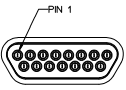
フロントGPIOコネクタは、MOLEX 83612-9020コネクタの形式で提供されます。このコネクタには、適合する既製の中継用MOLEX D-Subケーブル(MOLEX 083422-9018)が用意されています。
| ピン番号(3P FPGA) | 絶縁型 | 信号 | 基準信号 |
|---|---|---|---|
| 1 | いいえ | GPO 0 (TTL) | 5 VDC / グローバルGND(ピン6) |
| 2 | いいえ | GPO 1 (TTL) | 5 VDC / グローバルGND(ピン6) |
| 3 | いいえ | RS485(GND)用に予約済み | |
| 4 | いいえ | RS485用に予約されています | |
| 5 | いいえ | 5 V_OUT(最大0.5 A) | |
| 6 | いいえ | GND(グローバルGND) | |
| 7 | いいえ | — | |
| 8 | はい | GPI 2(差動信号に使用する場合はGPI2+) | GPI電圧IN(ピン10)/ GPI GND(ピン15) |
| 9 | はい | GPI 3(差動信号に使用する場合はGPI2-) | GPI電圧IN(ピン10)/ GPI GND(ピン15) |
| 10 | はい | GPI電圧IN(4.5~28 VDC) | |
| 11 | はい | GPI 0+ | GPI電圧IN(ピン10)/ GPI GND(ピン15) |
| 12 | はい | GPI 0- | GPI電圧IN(ピン10)/ GPI GND(ピン15) |
| 13 | はい | GPI 1+ | GPI電圧IN(ピン10)/ GPI GND(ピン15) |
| 14 | はい | GPI 1- | GPI電圧IN(ピン10)/ GPI GND(ピン15) |
| 15 | はい | GPI GND |
可能なトポロジ#
imaWorx CXP-12 Quadは次のように操作できます。
| カメラの 数 | チャンネルの 数 | トポロジー |
|---|---|---|
| 1 | 1 | 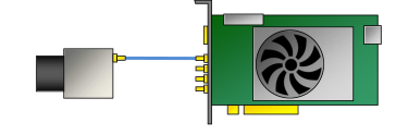 |
| 1 | 2 | 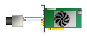 |
| 1 | 4 | 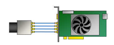 |
| 2 | 2 | 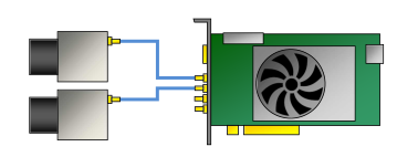 |
| 2 | 3 | 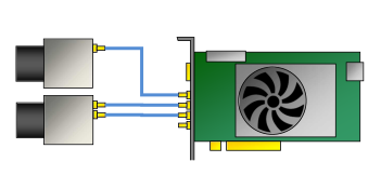 |
| 2 | 4 | 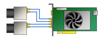 |
| 3 | 3 | 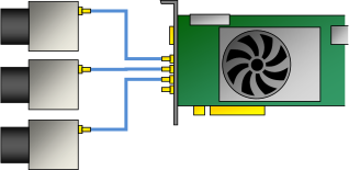 |
| 3 | 4 | 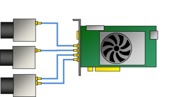 |
| 4 | 4 | 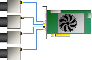 |
常に12 Vを供給するPCIe 6ピンコネクタを介してコンピュータの電源に接続されている場合、imaWorx CXP-12 QuadはPower over CXP (PoCXP)をサポートします。
カメラはどのような順序でも接続できます。
情報
1台のホストコンピューターで複数の imaWorx CXP-12 Quad ボードを使用する場合は、ボードごとに PCIe Gen. 3.0 x8 スロット以上が空いていることを確認してください。詳細については、Using Multiple Boards in one Hostを参照してください。
どのトポロジーをどのアップレットで使用できるかについては、Choosing the Right Area Scan AppletまたはChoosing the Right Line Scan Appletを参照してください。
取得アプレット#
システムリソースの最適な使用を確実にするため、imaWorx CXP-12 Quad用に設計されたすべての画像取り込みおよび処理機能が同時にimaWorx CXP-12 Quadにロードされるわけではありません。その代わりに、特定のアプリケーション分野の要件を満たすように組み合わされた、特定の画像取り込みおよび処理機能のさまざまなコンパイルがBaslerによって提供されます。
通常、アプレットは特定のカメラインターフェース規格とトポロジ、特定の画像取得機能、および場合によっては特定の画像(前)処理機能をサポートします。
アプレットには、Baslerが常に提供する Acquisition Applets(*.dll)と、Enhanced Appletsの2種類があります。
- Enhanced Appletsは、imaWorx CXP-12 Quadで使用できる、すぐに使える新しい一連のアプレットです。Enhanced Appletsは Acquisition Applets と Custom Applets の架け橋となるものであり、画像および信号データの取得・前処理、ならびにシステム情報の処理のための機能が含まれています。これらは、Binning、Flat-Field Correction、PGI機能を提供します。利用可能な Enhanced Applets の概要については、Enhanced Applets (imaWorx CXP-12 Quad)をご覧ください。
- 提供されている Acquisition Applets の詳細については、Acquisition Applets for imaWorx CXP-12 Quadを参照してください。
- 提供されている Acquisition Applets(GenTL および Fglib)のPDFドキュメントについては、Acquisition Applets for imaWorx CXP-12 Quad Documentationを参照してください。
注意事項#
→ Safety Instructions (Frame Grabbers)を参照してください。
インストール#
→ Connecting Frame Grabbersを参照してください。
→ Connecting Camerasを参照してください。