Memory要素#
This topic explains how memory operators in a VisualApplets design map to physical memory on the target hardware, and when you use which type. After you have read this topic, you understand the difference between FPGA-internal memory (for example block RAM) and frame grabber DRAM, how FIFO-style buffers differ from random-access frame buffers, how shared DRAM bandwidth limits designs with several RAM operators, and how you recognize memory-related problems in simulation and on hardware.
主要用語
FillLevel tells you how full a buffer is (in percent) at runtime on the hardware, for example in microDisplay X. A buffer that stays near 100% often points to a bottleneck or deadlock. As a starting point, place a buffer after the camera.
For platform RAM sizes, data widths, and bandwidth values, see Device Resources.
FPGA Memory vs. Frame Grabber DRAM#
VisualApplets memory operators fall into two groups by where they store data on the frame grabber. A second distinction is how they access that data: FIFO-style buffers versus random-access or multi-ROI frame buffers. The Overview of the Memory Library in the Operator Reference shows where each memory operator stores its data. The RAM resource in VisualApplets is a device-resource token that maps to board DRAM. It is not memory inside the VisualApplets application.
| Property | FPGA-internal memory | Frame grabber DRAM |
|---|---|---|
| Typical operators | ImageFifo; 小規模なランダムアクセスのケースにも FrameMemoryRandomRd / LineMemoryRandomRd | ImageBuffer, LineBuffer, FrameBufferRandomRead, FrameBufferMultiRoi, FrameBufferMultiRoiDyn |
| Location | Inside the FPGA (BRAM, LUT RAM, or URAM on imaFlex CXP-12 Quad/Penta) | On the board, outside the FPGA |
| 容量 | 制限あり。フル解像度のフレームは利用可能なFPGA Memoryを超えることがよくあります | より高い。多くのラインまたはフルフレームに適しています |
| レイテンシー | 低い。外部DRAMバスへのアクセスはありません | ライン指向のFIFOは少なくとも1つのラインを追加します |
| VisualApplets RAMリソース | いいえ — RAMデバイスリソースを予約しません | はい — インスタンスごとに1つのRAMリソースがあり、ボードDRAMにマッピングされます |
| 帯域幅 | ローカル。オペレーターはフレームグラバーのRAMインターフェースを競合しません | 同じ物理インターフェース上のRAMオペレーター間で共有されます — Sharing DRAM Bandwidthを参照してください |
Choosing a Memory Operatorの表を使用してオペレーターを選択し、パラメータとプラットフォームの詳細について対応するオペレーターセクションをお読みください。
Choosing a Memory Operator#
| 使用事例 | 優先 |
|---|---|
| 小型バッファ、低レイテンシ、DRAM帯域幅コストなし | ImageFifo (FPGA内部) |
| mE5上のImage FIFO、ピーク吸収、ROI | ImageBuffer (DRAM) |
| imaFlex CXP-12 Quad/Penta上のLine FIFO | LineBuffer (DRAM) |
前のバッファ SYNC わずかな遅延を伴う | ImageFifo (または遅延が大きい場合はより大きなDRAMバッファ) |
| ランダムピクセル読み取りによるフルフレームストア | FrameBufferRandomRead (DRAM) |
| 1つのバッファからの複数または動的なROI | FrameBufferMultiRoi / FrameBufferMultiRoiDyn (DRAM) |
設計ガイドライン
カメラからのデータバーストを補償するために、デザイン内で少なくとも1つのDRAMオペレーターを使用することをBaslerはお勧めします。そのDRAMバッファは、デフォルトのカメラデカップリングパスです(LineBuffer または ImageBufferを使用します。 ImageFifo は、カメラのバーストを吸収する必要がある場合に、そのDRAMバッファの代わりにはなりません。
ImageFifo#
イメージ ImageFifo オペレーターは画像データを 先入れ先出し(first-in, first-out) バッファとしてFPGA内部Memoryにキューイングします。バッファのサイズは EntitiesToStore および EntityType パラメータ。 EntityType の値を持っています PIXEL, LINE、または FRAME。出力が空いている場合、データはすぐに転送されます。下流のモジュールがブロックされている場合、バッファはいっぱいになります。
パラメーターを InfiniteSource の ImageFifo オペレーターを使用して ENABLED カメラなどの停止不能なソースから入力が供給される場合。
情報
イメージ ImageFifo オペレーターは比較的少数のピクセルのみをバッファリングします。そのため、FIFOオーバーフローが発生するリスクが非常に高く、オペレーター側で内部的に常に堅牢に処理されるとは限りません。停止不能なストリームの場合、Baslerでは次の組み合わせを推奨しています。 ImageFifo 先行する Overflow オペレーターと組み合わせるか、 ImageFlowControl オペレーターを使用します。代わりに ImageFifo オペレータを使用します。 ImageFlowControl オペレーターは、FIFOバッファリングと統合されたオーバーフロー処理を組み合わせます。
パラメーターを使用して、 ImplementationType を選択できます。 AUTO (デフォルト)、 BRAM, LUTRAM、または imaFlex CXP-12 Quad/Penta では URAM. Basler recommends that you always use AUTO 特定のFPGAリソースタイプが不足しない限りは。
オペレーターの詳細については、Operator ReferenceのImageFifoを参照してください。
ImageBuffer and LineBuffer#
イメージ ImageBuffer (microEnable 5)および LineBuffer (imaFlex)オペレーターは次のように動作します: ライン指向の FIFO: 選択された ROI 内の完了したラインは、後段のモジュールが受け入れ可能になり次第すぐに転送されます。レイテンシは少なくとも 1ラインです。出力がブロックされてバッファが満杯になると、レイテンシが増加します。以下も参照してください。 レイテンシー チュートトリアルのトピック。
Platform Note: ImageBuffer vs. LineBuffer#
| オペレーター | プラットフォーム |
|---|---|
ImageBuffer | microEnable 5(mE5) |
LineBuffer | imaFlex CXP-12 Quad / Penta |
imaFlex CXP-12 Quad および Penta はサポートしていません the ImageBuffer オペレーター。デザインを mE5 から imaFlex に変換する際、VisualApplets は 置き換えます 各 ImageBuffer オペレーターは、imaFlexプラットフォームに対して同じコアバッファリングおよびROI機能を提供します。 LineBuffer オペレータを使用します。 LineBuffer オペレーター。
Defining Regions of Interest (ROI) with ImageBuffer and LineBuffer#
次を使用することで、 ImageBuffer および LineBuffer オペレーターを使用すると、関心領域(ROI)も定義できます。これを行うには、次を設定します。 XOffset, XLength, YOffsetおよび YLength パラメーター。エッジケースはオペレーターリファレンスに記載されています。たとえば、入力が要求されたROIよりも小さい場合や、デザインが以下の場合などです。 Line1D モードの場合、または余分なピクセルに対して未定義のコンテンツが含まれている場合。
オペレーターの詳細については、オペレーターリファレンスの LineBuffer および ImageBuffer を参照してください。
Monitoring Buffer Usage and Overflow#
イメージ ImageBuffer および LineBuffer オペレータは、バッファの使用状況とオーバーフローを監視するための次のステータスパラメーターを提供します。
| パラメーター | 意味 |
|---|---|
FillLevel | バッファ RAM の使用率をパーセントで定義します(対象 ImageBuffer 25% 刻み)。 |
LineCount | 格納されている現在のライン数を示します。でのみ利用可能です LineBuffer オペレータ。 |
Overflow | 容量を超えずにバッファがこれ以上データを受け入れられないことを示します。このステータスパラメータは、Synchronization ライブラリ内の Overflow Synchronization ライブラリのオペレーターであり、算術オーバーフローと同じではありません。以下を参照してください。 停止可能および停止不可能なデータストリーム チュートリアルのトピックおよび ビット演算 チュートトリアルのトピック。 |
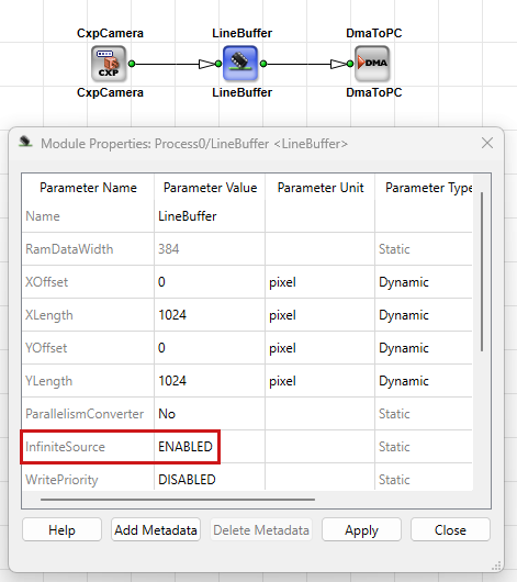
オーバーフローが発生した場合、受信データが破棄され、有効な画像ハイトが削減される可能性があります。オペレーターが回復するまで、不完全な画像が Memory に残る場合があります。 Overflow ソースが停止不能な場合に適用され、 InfiniteSource です。 ENABLED。設定 InfiniteSource を ENABLED バッファがカメラまたは別の無限ソースの直後に配置されている場合。以下も参照してください。 停止可能および停止不可能なデータストリーム チュートリアルのトピック。デバッグ時にこれらのパラメータを使用する方法については、以下を参照してください。 Recognizing Memory-Related Errors.
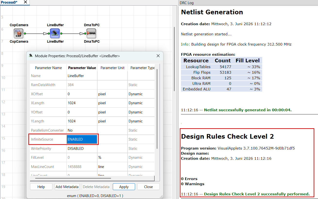
対象 LineBuffer オペレータでは、Basler は以下の有効化を推奨します。 WritePriority パラメータ、一時的な書き込みレートが利用可能な DRAM 帯域幅を超える場合、カメラからの書き込みバーストは読み込みよりも優先されます。平均帯域幅は、そのオペレータが利用できる共有の範囲内に収まる必要があります。 InfiniteSource です。 ENABLED。もし WritePriority です。 ENABLED一時的な書き込みレートが利用可能な DRAM 帯域幅を超えている間は、カメラからの書き込みバーストが読み込みよりも優先されます。the 平均 帯域幅は、そのオペレーターに割り当てられた利用可能な共有内に収まる必要があります。
イメージ LineBuffer オペレータは、モジュールパラメータを使用して入力と出力の間で Parallelism を変換することもできます。 ParallelismConverterそのため、常に別々の PARALLELup / PARALLELdn。以下も参照してください。 Parallelism チュートトリアルのトピック。
Full Frames, Random Access, Multi-ROI with the FrameBuffer Operators#
イメージ FrameBufferRandomRead, FrameBufferMultiRoiおよび FrameBufferMultiRoiDyn オペレーターは格納します 完全な画像または大きな領域 読み出し順序を変更できます。 行いません 厳密なラインFIFO。ランダムピクセルアクセスや、1つのバッファからのMultiple ROIが必要な場合に使用します。
FrameBufferRandomRead#
FrameBufferRandomRead 入力画像をDRAMに書き込み、次のようにピクセルを読み出します。 列および行のアドレス 専用のアドレスポート経由。幾何学変換、リマッピング、その他のランダムアクセスパターンに使用します。
小さなフレームやラインの場合は、DRAM オペレータではなく、次のような FPGA 内部のオペレータを使用することを推奨します。 FrameMemoryRandomRd または LineMemoryRandomRd 。
オペレーターの詳細については、オペレーターリファレンスのFrameBufferRandomReadを参照してください。
FrameBufferMultiRoi and FrameBufferMultiRoiDyn#
イメージ FrameBufferMultiRoi および FrameBufferMultiRoiDyn オペレーターは画像データを保存し、以下を出力します。 複数の関心領域(ROI). FrameBufferMultiRoiDyn 有効化します 動的な コントロールリンクからのROIサイズと位置。
Sharing DRAM Bandwidth#
各DRAMオペレーターには、RAMタイプのVisualAppletsリソースが1つ必要です。このリソースは、VisualAppletsリソースモデル内のスロットです。フレームグラバー上の物理DRAMにマッピングされます。imaFlexおよびmicroEnable 5 marathonプラットフォームでは、RAMリソースを予約するすべてのオペレーターが物理DRAMを共有します。各オペレーターには専用の重ならないメモリ領域が割り当てられますが、サイズと帯域幅は同じ物理インターフェース上のアクティブなRAMオペレーター間で分割されます。
結果:
- すべての読み出しおよび書き込みは、共有インターフェース上の帯域幅を消費します。
- 複数のDRAMインスタンスを使用する場合やスループットが高い場合、総トラフィックがプラットフォームの制限を超える可能性があります。
- 過剰な要求はブロッキングや
FillLevelの増加、オーバーフロー、または持続可能なフレームレートの低下につながります。
Device Resourcesで、お使いのプラットフォームのRAM size、RAM data width、RAM bandwidth total (shared)を確認してください。
必要な場合は、Resourcesダイアログでリソースを割り当てます。Device ResourcesのAllocation of Device Resourcesを参照してください。
Bandwidth Calculation Notes#
RAM sizeとRAM data widthを効率的に使用する方法については、Shared Memoryアプリケーションノートで説明しています。
重要ポイント:
-
読み出しと書き込みでインターフェースを共有します。単一のDRAMオペレーターの場合、利用可能な画像データレートを予測する際に、プラットフォームの最大帯域幅を2で割って(書き込みに半分、読み出しに半分)、効率係数を適用します。記載されている帯域幅の値は理論上の最大値であり、実際の効率はそれより低くなります。
-
RAM data widthをできる限り最大限に活用してください。リンクの実効RAM data widthは次のとおりです。
bit width × Parallelism × kernel elements
その積は、各DRAMアクセスの実効幅になります。Parallelism × Base Design Clockによるピクセルレートの帯域幅と混同しないでください。DRAMの最大スループットは、ボードに応じて、たとえば256 bit、384 bit、640 bitなど、積がプラットフォームのRAM data widthに一致し、それを超えないときに達成されます。積を最大RAM data widthに一致させると、DRAMの書き込みおよび読み出し帯域幅がフルに活用されます。値が大幅に低い場合、DRAMアクセスがボトルネックになる可能性があります。8 bit × Parallelism 4の設計では、256ビットインターフェースのうち32 bitしか使用せず、帯域幅の余裕が無駄になります。
-
複数のDRAMオペレーターで帯域幅が共有されます。共有メモリプラットフォームでは、1つのオペレーターで使用できる帯域幅は、そのインターフェース上の1 / (RAMオペレーター数)にほぼ比例してスケールします。詳細はプラットフォームによって異なり、Device Resourcesおよびアプリケーションノート:Shared Memoryに記載されています(Related Topicsを参照)。
-
プラットフォームに複数の物理インターフェース(imaFlex 2 Dual 100など)が備わっている場合は、独立したRAMバンク間でオペレーターのバランスを取ります。帯域幅は、同一の物理バンク上のオペレーター間でしか共有されません。
設計ガイドライン
RAMの使用計画は早めに立ててください。DRAMオペレーターを追加するたびに、同じ物理メモリインターフェイス上の他のオペレーターで使用できる帯域幅が減少します。別のDRAMバッファを追加する前に、結合された読み取り/書き込みトラフィックを計算し、プラットフォームで使用可能な共有帯域幅と比較してください(「Device Resources」を参照)。不要にDRAM帯域幅を消費しないように、小規模なデカップリングタスクには ImageFifo (FPGAメモリ)を優先的に使用してください。
Recognizing Memory-Related Errors#
VisualAppletsでは、すべての実行シナリオに対して、設計に適切なタイプとサイズのメモリが十分にあるかどうかを常時検証できるわけではありません。画像寸法、レート、同期の要件に一致するオペレーターとバッファサイズを選択する必要があります。
ハードウェアに対してバッファサイズが小さすぎる場合でも、シミュレーションは正常に実行されることがあります。シミュレーションでは問題なく見えても、フレームグラバー上では「SDKで画像が出力されない」といった障害がしばしば発生します。
一般的な原因は、 SYNC デッドロック および メモリの不足または誤り.
これらの問題を回避するために、次のチェックを行ってください。
- バッファとDMAパスの配線後、Design Rules Check Level 1 and Level 2を実行します。
- ハードウェア上で
FillLevel(および利用可能な場合はOverflow)を確認してください(microDisplay Xなど)。Fillが常に100%になる状態は、多くの場合、デッドロックまたは帯域幅のボトルネックを示しています。 - 複数のDRAMオペレーターを使用する場合は、Design → Device Resourcesを開き、RAMの割り当てと想定される帯域幅のシェアを確認します。
- 無限ソースの場合は、
InfiniteSourceです。ENABLED停止不可能なストリームを受け入れるすべてのバッファで確認してください。
一般的なパイプラインの例#
Camera to DMA Through a DRAM Line Buffer#
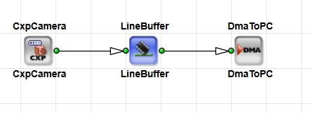
最小限の構成のデザインには、1つのカメラオペレータ、 InfiniteSource が次のように設定されている場合: ENABLEDを持つ1つのDRAMバッファ、および1つの DmaToPC オペレーター:
が含まれます。このバッファを使用してピークを吸収し、ラインベースの処理にデータを供給します。ハードウェア上で FillLevel ハードウェア上の値。100%近い値で推移する場合は、多くの場合ボトルネックやデッドロックを示しています。参照: Recognizing Memory-Related Errors.
Camera Through LineBuffer into a 3×3 Kernel#
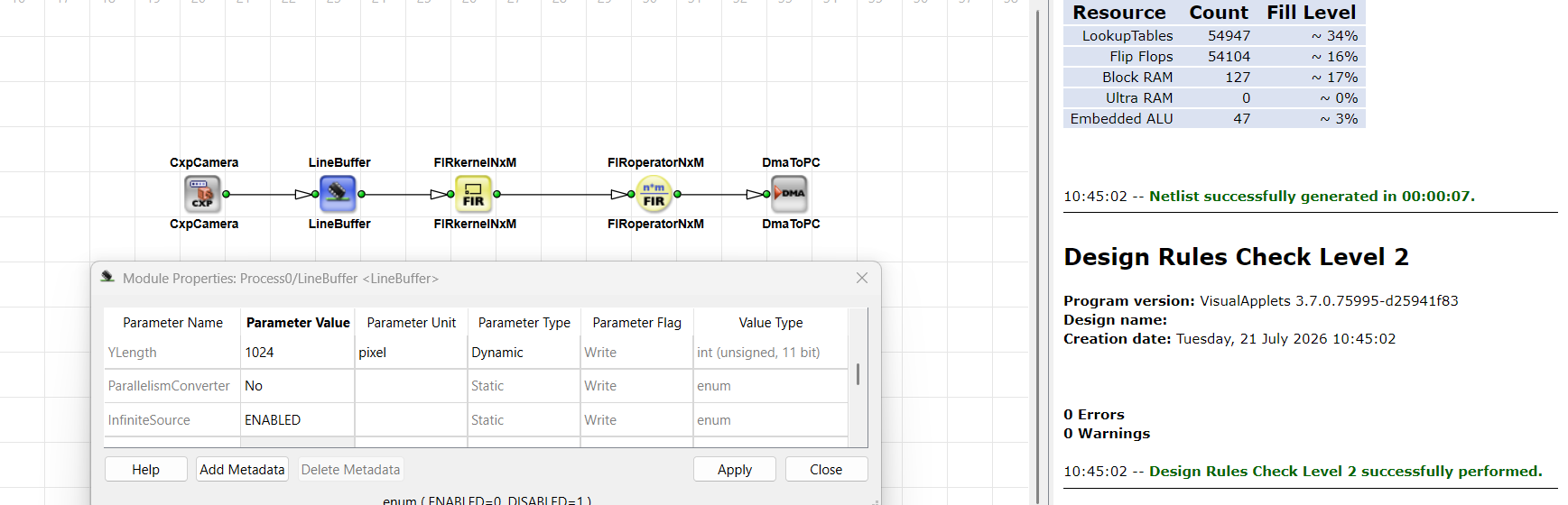
以下のデザインでは、DRAMバッファが近傍演算オペレータ(3×3など)にラインを供給してカーネルを構築します。このバッファにより、少なくとも1ラインのレイテンシ(フィルタパスのブロックによるバッファフルが発生した場合はそれ以上)が追加されます。また、 LineBuffer オペレータの共有DRAM帯域幅についても考慮してください。スクリーンショットのDesign Rules Checkにより、ビルド前にリンクフォーマットとバッファ設定の一貫性が確認できます。
関連トピック#
- 停止可能および停止不可能なデータストリーム チュートリアルトピック —
InfiniteSource、オーバーフロー、カメラのデカップリング - Parallelism チュートトリアルのトピック — 帯域幅、RAMデータ幅、
LineBufferの変換 - Latency チュートリアルのトピック — バッファオペレーターのラインレイテンシ
- オペレータータイプと同期 チュートリアルのトピック — 次の処理前のバッファ:
SYNC - Device Resources — プラットフォームRAMとShared Memory Concept
- Shared Memory アプリケーションノート — 効率的なDRAM使用法と帯域幅の例
- オペレーターリファレンスのMemory Library — メモリタイプ別のオペレーター概要