Python Command Reference#
Info
This reference describes Python functions for designing, simulating, and building VisualApplets designs in an embedded Python interpreter. All Python functions documented here are case sensitive. Use forward slashes (/) for file paths and for specifying hierarchical paths in design elements.
Position Parameters in Diagrams Whenever a function expects a position in the design window, a Python tuple (x, y) is used.
Port/Link Identification Links and module ports are identified via the tuple (full_module_name, port_name). full_module_name has the following syntax: <HierLevelPath>/<ModuleName>.
<HierLevelPath>specifies the path to the hierarchical level in the design where the module is located. Start on process level. Use forward slashes.<ModuleName>specifies the name of the module you want to delete.
Return Values Unless otherwise noted, functions return None if there’s nothing special to return. Some do return specific data (e.g., lists, strings) for queries.
Enumeration-Type Parameters In some function calls, certain parameters can be an enumeration type (e.g., LinkParam.Arithmetic, LinkParam.ColorFlavor, etc.) or a string name of that member. For example, SetLinkParams can accept either an enum member (e.g., Arithmetic.UNSIGNED) or a string (e.g., "UNSIGNED").
File Overwrite Behavior Functions that write files (e.g., SaveDesign, ChangePlatform) may include a boolean parameter such as overwrite=False. If False, attempting to overwrite an existing file may raise an exception.
Creating, Loading, and Saving Designs#
LoadDesign#
| Command Syntax |
|---|
LoadDesign (file_name: str) |
Example
LoadDesign("c:/VA_Python/BaseAreaGray8.va")
If there is already a design loaded: Close the currently loaded design via command CloseDesign before using command LoadDesign.
CreateDesign#
| Command Syntax |
|---|
CreateDesign (design_name: str, platform_name: str) |
Command for creating a new design with the name for a hardware platform. For specifying the target platform of the design, you can either use
- the VisualApplets library name for the platform (e.g., "iF-CXP12-Q"), or
- the full name of the platform (e.g., "imaFlex CXP-12 Quad").
Example
CreateDesign("MyNewProject", "iF-CXP12-Q")
SaveDesign#
| Command Syntax |
|---|
SaveDesign (file_name: str, overwrite: bool = False) |
Command for saving a design under file_name. Specify in file_name the path to the file and the file name itself. Use slashes for indicating the path to the design file.
Don't forget to add the file name extension to the file name.
- If you specify file extension *.va or *.vad, your design is saved in the standard VisualApplets design format. All contents of the file are saved. Use the *.vad file format as primary data format for your VisualApplets designs.
If you want to overwrite an existing file, set the optional parameter overwrite to True.
Example
SaveDesign("c:/VA_Python/Project1.va")
ChangePlatform#
| Command Syntax |
|---|
ChangePlatform (platform_name: str, file_name: str, overwrite: bool = False) |
Command for converting the current design to another hardware platform platform_name and saving the converted design as file_name.
Specify the name of the desired hardware platform in parameter platform_name. For specifying the target platform of the design, you can either use
- the VisualApplets library name for the platform (e.g., "iF-CXP12-Q"), or
- the full name of the platform (e.g., "imaFlex CXP-12 Quad").
Specify in file_name the path to the file (using forward slashes), the file name itself, and the file name extension. If you want to overwrite an existing file, set the optional parameter overwrite to True.
Example
ChangePlatform("iF-CXP12-Q", "c:/VA_Python/ConvertedDesign.va")
CloseDesign#
| Command Syntax |
|---|
CloseDesign (discard: bool = False) |
Command for closing the currently open design.
If you set the optional parameter discard to True, the design will be closed even if it contains changes that you didn't save yet. The unsaved changes will be discarded.
If the parameter discard is set to False, and the design containes changes that you didn't save yet, the command will be terminated and you receive an according error message.
Example
CloseDesign(discard=True)
SetDesignProperty#
| Command Syntax |
|---|
SetDesignProperty (key: DesignProperty | str, value: str) |
Use this command to enter design properties for the currently loaded design.
There are four keys you can use:
ProjectName(the name you want the project to give)Version(version of the design)Description(description of the project).-
TargetRuntime(specify here the operating system that will be used on the host PC(s) running this applet on the frame grabber.)The following values are allowed:
- Win64
- Win32
- Linux64
- Linux32
The other enums of DesignProperty (e.g. Loaded) can't be set, but can only be read using GetDesignProperty().
Example
SetDesignProperty("TargetRuntime", "Win64")
SetDesignProperty(DesignProperty.ProjectName, "MyProject")
SetDesignClock#
| Command Syntax |
|---|
SetDesignClock (freq_in_MHz: float) |
Command for setting the basic clock frequency of the FPGA (in MHz).
Example
SetDesignClock(320.0)
Developing a Design#
CreateProcess#
| Command Syntax |
|---|
| CreateProcess ( ) |
Command for creating a new process. VisualApplets automatically numbers new processes.
Example
CreateProcess()
DeleteProcess#
| Command Syntax |
|---|
DeleteProcess (process_name: str) |
Command for deleting a process of the name process_name.
Example
DeleteProcess("Process1")
CreateModule#
| Command Syntax |
|---|
CreateModule (operator: str, full_module_name: str, mult: None | dict[str,int] = None, pos: tuple[int,int] = (0,0)) |
Command for creating an instance (module) of an operator OperatorType, and for positioning the module in the design window.
The command has two mandatory and two optional arguments:
operator: Name of the operator (e.g.,"BRANCH","NOP","Add", etc.).full_module_name: The hierarchical path plus the desired name for the module, e.g.,"Process0/MyModule".mult(optional argument): Use this argument to specify a multiplicity of ports.
For example:{"O": 3}creates 3 output ports on an operator with an output multiport named"O". See description below.pos(optional argument): A tuple(x, y)specifying where to place this new module in the design window.
Examples
# A BRANCH operator with 3 output ports, placed at (43, 123)
CreateModule("BRANCH", "Process0/branchz", {"O": 3}, (43, 123))

# A simple NOP operator at position (83, 163)
CreateModule("NOP", "Process0/myNop", pos=(83,163))
Using the optional parameter mult:
Many operators are instantiated with a fix number of ports. On the other hand, there are operators with a variable number of ports. During instantiation of an operator with a variable number of ports, you can define how many ports the module will have.
For example, when instanciating operator BRANCH, you can define how many output ports the instance will have:
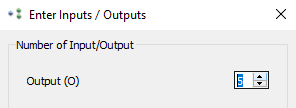
Thus, the number of output ports O is variable. Ports that have a variable number of ports we call multiports.
Multiports are identified via their base name. In BRANCH, for example, the base name of the output ports is O. Via an index that is added to the base name, a specific port can be identified and addressed:
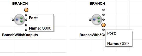
When using command CreateModule, you can use the optional argument mult to specify the multiplicity of the vector inputs and the vector outputs of a module with a dictionary where the key is the base name of the port and its value is the number of ports. This way, you can define the number of ports in instances (modules) of operators that have a variable number of ports, like, for example, operators BRANCH or ADD.
Example
CreateModule("BRANCH", "Process0/branchz", {"O": 3}, (43, 123))
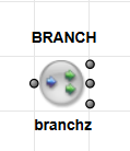
Defaults: If you don't use mult, the module is created with the default number of inports and outports. How many ports are created per default depends on the operator type.
Example
CreateModule("BRANCH", "Process0/branch", {}, (43, 123))
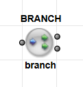
The default number of ports is created, 1 input and 2 output ports.
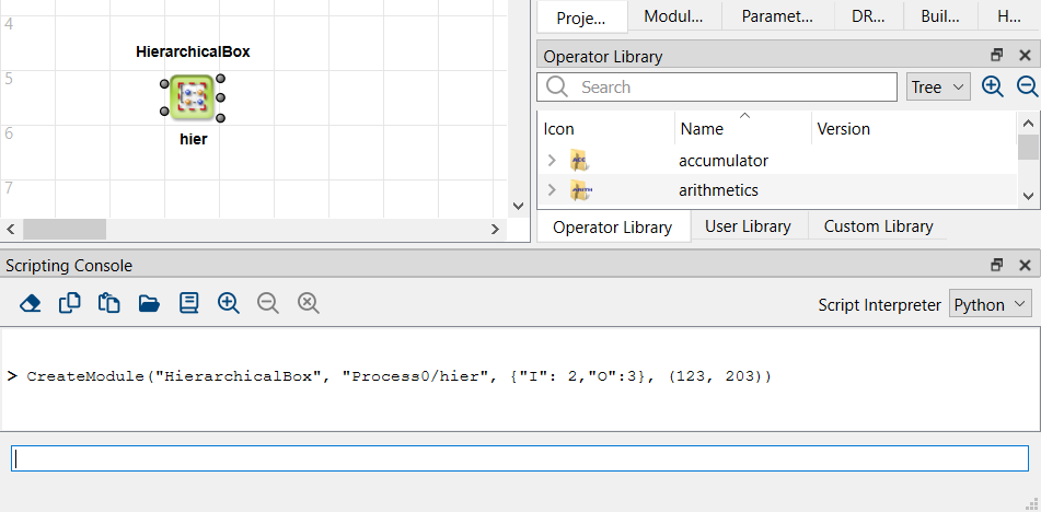
Example
CreateModule("HierarchicalBox", "Process0/hier", {"I": 2,"O":3}, (123, 163))
InstUserLibOperator#
| Command Syntax |
|---|
InstUserLibOperator (library: str, operator: str, full_module_name: str, pos: tuple[int,int] = (0,0)) |
Command for instantiating a user library element. Specify the user library via the parameter library, the name of the element (operator) in the library via the parameter operator, the name you want to give the module in your design and where you want to place the module in the hierarchy via the parameter full_module_name, as well as the position of the module in the design window via the optional parameter pos.
Example
InstUserLibOperator("MyUserLib", "MyOperator", "Process0/MyModule", (100,100))
InstCustomLibOperator#
| Command Syntax |
|---|
InstCustomLibOperator (library: str, operator: str, full_module_name: str, pos: tuple[int,int] = (0,0)) |
Command for instantiating a custom library element. Specify the user library via the parameter library, the name of the element (operator) in the library via the parameter operator, the name you want to give the module in your design and where you want to place the module in the hierarchy via the parameter full_module_name, as well as the position of the module in the design window via the optional optional parameter pos.
Example
InstCustomLibOperator("MyCustomLib", "MyOperator", "Process0/MyModule", (100,100))
DeleteModule#
| Command Syntax |
|---|
DeleteModule (full_module_name: str) |
Command for deleting the module full_module_name.
Simulation modules can't be deleted via this command. For deleting simulation modules, use the command DeleteSimModule.
Example
DeleteModule("Process0/Branch1")
ConnectModules#
| Command Syntax |
|---|
ConnectModules (from_port: tuple[str,str], to_port: tuple[str,str], x1: int|None = None, y2: int|None = None, x3: int|None = None) |
Command for connecting module ports.
The parameters from_port and to_port are tuples with the syntax: (full_module_name, port_name).
full_module_name has the following syntax: <HierLevelPath>/<ModuleName>.
Example
ConnectModules(("Process0/CxpCamera", "O"),("Process0/FrameBufferMultiRoi", "I"))
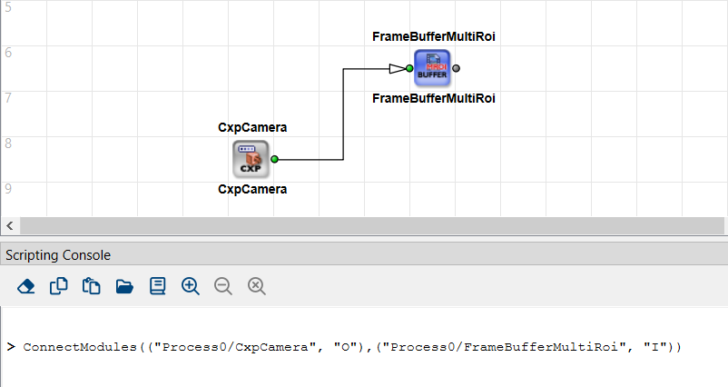
Via the optional parameters x1, y2, and x3 you can define the geometry of the connecting polygon: horizontal line from from_port to position x1, vertical line to position y2, horizontal line to position x3, vertical line to height of to_port, horizontal line to to_port.
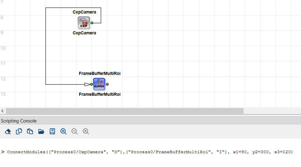
Examples
ConnectModules(("Process0/CxpCamera", "O"),("Process0/FrameBufferMultiRoi", "I"), x1=90, y2=300, x3=120)
DisconnectModules#
| Command Syntax |
|---|
DisconnectModules (port: tuple[str,str]) |
Command for deleting the link that is connected to port port.
Example
DisconnectModules(("Process0/cam1", "O"))
CreateComment#
| Command Syntax |
|---|
CreateComment (full_box_name: str, text: str, pos: tuple[int,int] = (0,0)) |
Command for creating a comment box.
The syntax of full_box_name is <HierLevelPath>/<BoxName>.
<HierLevelPath>defines the path to a specific hierarchical level in the design. Start on process level. Use forward slashes.<BoxName>specifies the name you want the comment box to have.
Example
CreateComment("Process0/MyComment", "This is my comment.", (400,400))
For the comment box content text you can use Unicode characters.
The position of the comment box in the design window you define via the parameter pos.
The return value of function CreateComment is full_box_name (the full hierarchical path to the comment box including the name of the comment box).
DeleteComment#
| Command Syntax |
|---|
DeleteComment (full_box_name: str) |
Command for deleting the comment box full_box_name.
The syntax of full_box_name is <HierLevelPath>/<BoxName>.
<HierLevelPath>specifies the path to the hierarchical level in the design where the comment box is located. Start on process level. Use forward slashes.<BoxName>specifies the name of the comment box you want to delete.
Example
DeleteComment("Process0/MyComment")
Parameterizing Operators and Links#
SetModuleParam#
| Command Syntax |
|---|
SetModuleParam (full_module_name: str, param_name: str, value: str|int|float|list[int]|list[float], index: int = -1) |
Command for setting a module parameter.
Info
Use this command only for setting an existent parameter to a specific value. You can't use this command for creating metadata parameters. For creating new metadata parameters, use the command SetParamString instead.
Examples
SetModuleParam("Process0/module6", "XLength", 512)
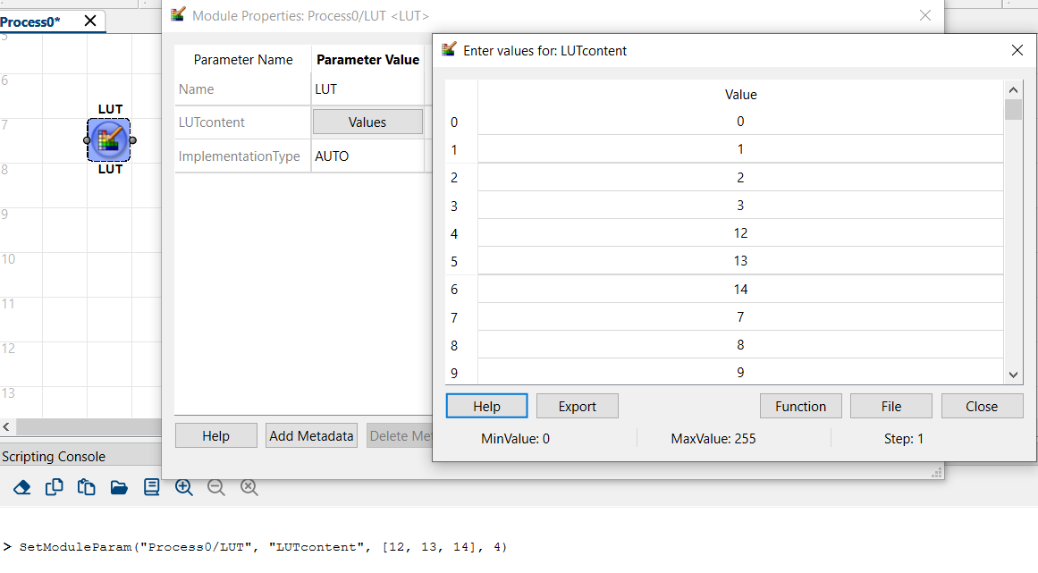
SetModuleParam("Process0/LUT1", "LUTcontent", [12, 13, 14, 15], 4)
Field parameters: For setting a field parameter, the index parameter must be provided.
Example for editing field parameters:
Before entering the command, the Enter values dialog looks as follows:
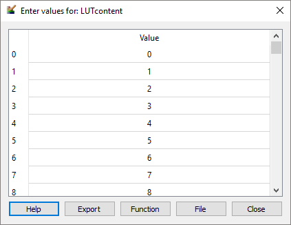
Entering the command
SetModuleParam("Process0/module3", "LUTcontent", [12, 13, 14], 4)
has the following result:
SetModuleParamProperty#
| Command Syntax |
|---|
SetModuleParamProperty (full_module_name: str, param_name: str, prop: ParamProperty|str, value: ParamTypeFlag|str|int|list[ParamTypeFlag]|list[str]) |
Command for changing the properties of a module parameter, e.g. making it dynamic or static. This command may replace SetModuleParamType. Single property names may have multiple values. You can change the following properties of prop:
-
access: One or more flags like:write: If the parameter can be switched in this direction, (for instance in the operatorLinkParamTranslator), it becomes a write-parameter.read: If the parameter can be switched in this direction, (for instance in the operatorLinkParamTranslator), it becomes a read-parameter.dynamic: If the parameter can be either dynamic or static, it hereby becomes a dynamic parameter.static: If the parameter can be either dynamic or static, it hereby becomes a static parameter.
-
position: An integer that defines the parameter's position among multiple parameters.
Example
# Make a parameter dynamic (if supported).
SetModuleParamProperty("Process0/LinkParamTranslator1", "MyParam", "access", ["dynamic", "write"])

# Reposition a parameter in a hierarchical box
SetModuleParamProperty("Process0/hierBox", "ParamA", "position", 3)
SetParamString#
| Command Syntax |
|---|
SetParamString (full_module_name: str, param_name: str, value: str) |
Use this command to define metadata parameters for a specific module.
Info
Don't use this command for setting an existent module parameter to a new value, even if the module parameter is of the type string.
For setting an existent module parameter to a new value, always use the command SetModuleParam in your scripts.
Example
SetParamString("Process0/MyModule", "MyNewMeta", "Some custom meta info.")
SetModuleParamType#
| Command Syntax |
|---|
SetModuleParamType (full_module_name: str, param_name: str, type_flag: ParamTypeFlag|str|list[ParamTypeFlag]|list[str]) |
Command for changing the type of a parameter. The following type flags are available:
Dynamic: If the parameter can be dynamic or static, this flag makes the parameter a dynamic parameter.Static: If the parameter can dynamic or static, this flag makes the parameter a static parameter.
Dynamic and Static mutually exclude each other.
Example
SetModuleParamType("Process0/MyOperator", "Threshold", "Dynamic")
SetLinkParams#
| Command Syntax |
|---|
SetLinkParams(link: tuple[str,str], param_dict: dict[LinkParam|str, int|<enum>|str]) |
Command for configuring the format of links, such as bit width, arithmetic mode, color format, etc. The link parameters can be identified either via the LinkParam enum (e.g. LinkParam.BitWidth), via the name of the enum (e.g. “BitWidth”) or via the name in the GUI (e.g. “Bit Width”).
link: Tuple for identifying the link via a connected module port `(, ) param_dict: A dictionary specifying parameter value pairs. The names of the link format parameters are the same as in the VisualApplets GUI. Example keys:LinkParam.BitWidth,"Arithmetic", etc.
Example
SetLinkParams(
    ("Process0/CreateBlankImage","O"),
    {
        "Parallelism": 4,
        "ImageProtocol": "VALT_LINE1D",
        "MaxImageWidth": "2048"
    }
)
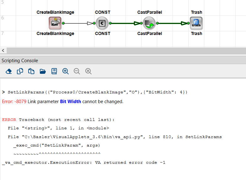
Info
When writing your Python script manually, the command is only applicable for parameters that can be changed. If you try to set a link parameter that cannot be changed, you will get an according error message:
SetResourceMapping#
| Command Syntax |
|---|
SetResourceMapping (full_module_name: str, resource_name: str, new_mapping: int, index: int = -1) |
Command for changing the mapping of resources to a module, e.g., "RAM". The resource resource_name will be mapped to the new index new_mapping. In case the module allocates multiple resources of the same type, use the optional parameter index for selecting the resource.
Example
SetResourceMapping("Process0/ImageBuffer", "RAM", 1)
SplitLink#
| Command Syntax |
|---|
SplitLink (link: tuple[str,str], number: int = 2) |
Command for creating a module BRANCH. The new branch module is inserted on the link that is identified by link. The new branch module has number outgoing ports. If you don't use the optional parameter number, the new branch module has two out ports.
The return value of function SplitLink is the full_module_name of the new branch module (full hierarchical path to the module, including the module name).
Example
branchName = SplitLink(("Process0/MyModule","O"), 3)
# branchName might be "Process0/BRANCH_1"
Querying Design Structure and Design Details#
GetDesignProperty#
| Command Syntax |
|---|
GetDesignProperty (key: DesignProperty|str) → str | bool |
This command retrieves design properties. You can use the following values for key:
ProjectName:name of the projectFileName: full path of the currently loaded design fileHardwarePlatform: library name of target hardware platform, for exampleiF-CXP12-QVersion: version of the designDescription: description of the projectTargetRuntime: specifies the operating system that will be used on the host PC(s) running this applet on the frame grabberLoaded: design is loaded; returns a boolean (True/False)
Design property Loaded can be requested while no design is loaded at all. This doesn't cause an error message. Requesting any other design property while no design is loaded causes an error message.
Example
val = GetDesignProperty("ProjectName")
print(val)  # e.g., "MyProject"
GetDesignClock#
| Command Syntax |
|---|
| GetDesignClock ( ) → float |
This command returns the basic clock frequency of the FPGA in MHz as float.
GetProcesses#
| Command Syntax |
|---|
| GetProcesses ( ) → list[str] |
This command returns a list[str] with the names of all processes of the design.
Example
processes = GetProcesses()
# e.g. ["Process0","Process1"]
GetSubModules#
| Command Syntax |
|---|
GetSubModules (hierarchy_name: str) → list[str] |
This command returns a list[str] with the names of the modules that are located in the requested hierarchy hierarchy_name.
For each sub-module, the full hierarchical name is listed.
Example
mods = GetSubModules("Process0")
GetParentHier#
| Command Syntax |
|---|
GetParentHier (full_element_name: str) → str |
This command returns the hierarchical name (full_module_name) of the parent of stated element full_element_name, that is, the full_module_name of the hierarchical element in which element full_element_name is located.
full_element_name can be a module, a simulation module, or a comment box.
Example
parent = GetParentHier("Process0/MyModule")
GetModules#
| Command Syntax |
|---|
GetModules (scope: SearchScope|ModuleScope|str, specifier: str, module_list: list[str]|None = None) → list[str] |
This command filters modules by certain criteria. The command returns a list with modules that have the characteristic you specify via scope and specifier. The list contains the full_module_name for all found modules (path to modules including the individual module name). If you don't want to search design-wide, but only in a specific set of modules, you can specify these modules in the optional argument module_list (via their full_module_name).
scope can have the following values:
"Pattern": Usespecifieras a wildcard expression forfull_module_name. If you state "*" as specifier, all modules of the design are returned."Flat": Usespecifieras a wildcard expression for thefull_module_nameof modules (like with "Pattern"). Hierarchical boxes will not be returned."Ordered": Returns all modules of the design. Usespecifierto define a sorting "Pattern". You have the following options:"path": modules are sorted by their position in the design graph (i.e., in the order of the data stream as it runs through the modules during simulation)."name": modules are sorted alphabetically by theirfull_module_name.
"OperatorType": Usespecifierto define the operator type of the modules you are looking for ("O", "M", "P", "O+P", "M+P", "unknown")."Operator": For getting all instances of a specific operator. Usespecifierto name the operator name (for example, "NOP")."LibraryType": Usespecifierto define a specific library type. All modules in the design that are instances of operators contained in libraries of this type are returned. The following values are allowed: operator, user, and custom (see alsoGetModuleProperty)."Library": Usespecifierto define a specific library. All modules that are instances of operators of this library are returned."Version": Usespecifierto define a specific operator version. All modules that are instances of operators of this version are returned.
Example
allModules = GetModules("Pattern", "*") # all modules
GetModulePorts#
| Command Syntax |
|---|
GetModulePorts (full_module_name: str, scope: PortScope|str) → list[str] |
This command returns a list[str] with the names of all ports of the specified module. You can use the optional parameter scope to filter for specific ports:
"Inputs": only the input ports are returned"Outputs": only the output ports are returned"All": all ports of the module are returned (default)
Example
inPorts = GetModulePorts("Process0/Branch1", "inputs")
GetModulePortProperty#
| Command Syntax |
|---|
GetModulePortProperty (port: tuple[str,str], prop: PortProperty | str) |
This command retrieves the properties of a module port. The following values for prop are available:
"IsConnected": Returns returns a boolean (True/False)."Position": Returns the position of the specified port in the diagram (design window) as a tuple (xPos,yPos). Ifportspecifies an inner hierarcical box node, for example, for example,("Process0/HBox","INBOUND#I000"), the position of this node within the hierarchical box design window is returned.
GetModuleProperty#
| Command Syntax |
|---|
GetModuleProperty (full_module_name: str, prop: ModuleProperty | str) → varies |
This command returns the properties of a module.
The following values for prop are available:
"Status": Returns an integer: Returns 0 if module isn't in error status; otherwise returns error code."Operator": Returns name of operator the module is an instance of, for exampleBRANCH."OperatorType": Returns operator type (O, P, M, unknown). "Unknown" is returned for hierarchical boxes and user library modules."LibraryType": Returns the library type of the library the operator stems from. One of the following values is returned:operator,user,custom."Version": Returns the version of the operator the module is an instance of."Type": Returns the module type. One of the following values is returned:process,hierBox,operator,user,custom."IsHierModule": ReturnsTrueif the stated module is capable of containing submodules; returnsFalseif the stated module cannot have sub-modules."IsProtected": ReturnsTrueif the module is an instance of a protected library element."Library": Returns the name of the library the operator stems from."Position": Returns the position in a design window as a list (xPos,yPos)."Resources": Returns a list of tuples (ResourceName, ResourceMapping)"Name": Returns the module name.
Example
operatorName = GetModuleProperty("Process0/MyModule", "Operator")
pos         = GetModuleProperty("Process0/MyModule", "Position")
GetModuleParams#
| Command Syntax |
|---|
GetModuleParams (full_module_name: str, select: list[str] | None = None) → dict |
Returns a dictionary where the keys are the parameter names and the values are given in a format depending on the value type:
Integer parameter: int Floating-Point parameter: float Enumeration parameter: str Field of integers: list[int] Field of floating-point parameters: list[float] String parameter: str
If you want to get all parameters of the module together with the currently set values, use command GetModuleParams only with parameter full_module_name.
Example:

If you want to get only the values of specific parameters, you can optionally limit the output with the optional parameter select.
Example:

Example
allParams = GetModuleParams("Process0/MyModule")
someParams = GetModuleParams("Process0/MyLUT", ["LUTcontent","ImplementationType"])
GetModuleParamProperty#
| Command Syntax |
|---|
GetModuleParamProperty (full_module_name: str, param_name: str, prop: ParamProperty | str) |
Command for retrieving parameter properties.
For the parameter prop, the following values are available:
"Status": Returns an integer: Returns 0 if module isn't in error status; otherwise returns error code."Type": Returns the parameter type asParamType, which may beParamType.Int,ParamType.Float,ParamType.Enum,ParamType.String,ParamType.IntField, orParamType.FloatField."Access": Returns whether the parameter is a read-only parameter or not: Returns parameter access asParamTypeFlagwhich may beParamTypeFlag.WriteorParamTypeFlag.Read."Unit": Returns the unit of the parameter."Range": For integer and float data types, the command returns the value range as a list containing the three entriesMin,Max,Step. For enum parameters, it returns a list of pairs of enum names and enum values."Size": Returns the size of the field. Only forIntFieldandFloatFieldparameters."IsDynamic": ReturnsTrueif the requested parameter is dynamic; otherwise returnsFalse."IsStatic": ReturnsTrueif the requested parameter is static; otherwise returnsFalse."IsEditable": ReturnsTrueif the requested parameter can be edited; otherwise returnsFalse."Position": Returns the position in the list of parameters as integer.
Example
rangeVal = GetModuleParamProperty("Process0/LUT1", "LUTcontent", "Range")
GetLinkParams#
| Command Syntax |
|---|
GetLinkParams (link: tuple[str,str], select: list[LinkParam|str]|None = None) → dict[LinkParam, (various)] |
Returns a dictionary where the keys are members of LinkParam and the values are given in a format depending on the key:
BitWidth: intArithmetic: ArithmeticParallelism: intKernelColumns: intKernelRows: intImageProtocol: ImageProtocolColorFormat: ColorFormatColorFlavor: ColorFlavorMaxImageWidth: intMaxImageHeight: int
Use the optional select parameter for providing a list of link parameters for a specific query of those parameters.
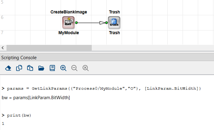
Example:
Example
params = GetLinkParams(("Process0/MyModule","O"))
bw = params[LinkParam.BitWidth]  # e.g. 8
Example
params = GetLinkParams(("Process0/MyModule","O"), [LinkParam.BitWidth])
bw = params[LinkParam.BitWidth]  # e.g. 8
GetLinkParamProperty#
| Command Syntax |
|---|
GetLinkParamProperty (link: (str, str), param: LinkParam | str, prop: ParamProperty | str) → varies |
This command retrieves the properties of a specific link parameter.
The following values for the parameter prop are possible:
Status: Returns an integer: Returns 0 if module isn't in error status; otherwise returns error code.IsEditable: ReturnsTrueif parameter value can be changed; otherwise returnsFalse.Range:- For integer data types, the command returns the value range either as a tuple containing three elements (Min, Max, Step), or as a tuple containing all allowed values. You distinguish the two kinds of tuples as follows: The Min-Max-Step tuple contains 3 tuple elements; the third tuple element is smaller or equal to the second tuple element. A tuple stating all allowed values starts with the smalles value and ends with the highest value. If only one value is allowed, the value is returned in format {value value 1}, for example, { 4 4 1} for min=4, max=4, step=1.
- For enum parameters, the command returns a tuple of pairs of enum names and enum values.
Type: Returns the parameter type: ReturnsParamType.Enumfor the parametersLinkParam.Arithmetic,LinkParam.ImageProtocol,LinkParam.ColorFormat, orLinkParam.ColorFlavor. For any other link parameter,ParamType.Intis returned.
GetLinkProperty#
| Command Syntax |
|---|
GetLinkProperty (link: tuple[str,str], prop: LinkProperty|str) → varies |
This command returns a specific property of a specific link. If you address the port of a hierarchical box with the parameter link, the command works as long as there is a link to or from this port within the hierarchical box.
The following options for the parameter prop are available, where the return type depends on the parameter:
Status: Returns an integer: Returns 0 if module isn't in error status (i.e., if the parameter settings of the link source and the link target match, and the DRC doesn't find an error); otherwise returns error code.From: Returns the starting point of the link. The starting point can be either the out port of a foregoing module, or an inner hierarchical box node (INBOUND#...) the link is connected to. The command returns a tuple containing the two values<FullModulenname>and<PortName>.To: Returns the end point of the link. The end point can be either the in port of a following module, or an inner hierarchical box node (OUTBOUND#...) the link is connected to. The command returns a tuple containing the two values<FullModulenname>and<PortName>.Source: Returns the tuple containing the link stated bylinkfor all foregoing links up to the source of the link. The link chain is followed up backwards through the hierarchies, from the module you state in<FullModulenname>back to the starting point. The order of the elements within the returned list corresponds to the backward-course of the lookup (the source module is the last entry in the list).Dest: Returns a tuple containing the link stated bylinkfor all following links up to the target module of the link. The link chain proceeds forwards through the hierarchies, from the module you state in<FullModulenname>up to the end (sink). The order of the elements within the returned list corresponds to the forward-course of the lookup – the target module (destination) is the last entry in the list.HasConnectedSimModule: ReturnsTrueif a simulation module is connected to the link; returnsFalseif no simulation module is connected.ConnectedSimModule: Returns the hierarchical name of a connected simulation module.
Example
src = GetLinkProperty(("Process0/MyModule","O"), "To")
GetSimModules#
| Command Syntax |
|---|
GetSimModules (sim_type: SimModuleType|str, scope: SearchScope|str, specifier: str) → list[str] |
Returns the full names of simulation modules matching a given type/filter.
sim_typecan be"Source"or"Probe".scopecan be"Hierarchy"or""Pattern"".specifieris a string for the filter or hierarchy.
Example
simProbes = GetSimModules("Probe",""Pattern"","*")
GetCommentBoxes#
| Command Syntax |
|---|
GetCommentBoxes (scope: SearchScope|str, specifier: str) → list[str] |
This command retrieves comment boxes in a design. The command returns a list with all comment boxes that have the characteristic you specify via the parameters scope and specifier. The list contains the FullElmentNames (hierarchical names including box name).
scope: Can be"Hierarchy"or""Pattern"".specifier: Is the string "Pattern" or hierarchy name.
GetCommentProperty#
| Command Syntax |
|---|
GetCommentProperty (full_box_name: str, prop: CommentProperty | str) → str | tuple |
This command retrieves the properties of a comment box.
full_box_name has the following syntax: <HierLevelPath>/<BoxName>.
<HierLevelPath>specifies the path to the hierarchical level in the design where the comment box is located. Start on process level. Use forward slashes.<BoxName>specifies the individual name of the comment box.
prop has the following options:
Content: The content of the comment box is returned as a string.Position: the X and Y position of the left upper corner of the comment box in the design window are returned as a tuple.
Editing the Design – Further Commands#
Move#
| Command Syntax |
|---|
Move (item: tuple[str, str]|str, pos: tuple[int, int]) |
Command for re-positioning a module, a hierarchical box node, a comment box, or a simulation module to a new position within the design window.
itemcan be:- A string
"<FullModuleName>"for identifying a module, a comment box, or a simulation module. - A tuple
(<FullModuleName>, <HierNodeName>)for moving a hierarchical node, e.g.("Process0/Box1","INBOUND#I000"). posis(x, y).
Example
Move("Process0/MyModule", (100, 200))
Select#
| Command Syntax |
|---|
Select (item`: str|tuple[str, str]) |
Command for selecting a module, a simulation module, a comment box, or a link.
itemcan be either:- A string
"<FullModuleName>"to select a module, a simulation module, or a comment box by name. - A tuple
(<FullModuleName>, <PortName>)to select a link.
Example
Select("Process0/MyModule")
Select(("Process0/Branch1", "O"))
ClearSelection#
| Command Syntax |
|---|
ClearSelection (parent_hierarchy: str) |
Command for deleting a selection of elements (modules, hierarchical box nodes, links, comment boxes, or simulation modules).
Use the optional parameter parent_hierarchy to deselect all elements on the hierarchical level parent_hierarchy.
If you don't use parent_hierarchy, element selection is deleted globally, and after carrying out the command, no elements within the design are selected.
CopySelected#
| Command Syntax |
|---|
CopySelected (parent_hierarchy: str) |
Command for copying the selected elements on the hierarchical level parent_hierarchy. If you don't use the optional parameter parent_hierarchy, the selected elements on the hierarchical level of the currently active design window are copied.
DeleteSelected#
| Command Syntax |
|---|
DeleteSelected (parent_hierarchy: str) |
Command for deleting the selected elements on hierarchical level parent_hierarchy. Only the selected modules of the hierarchical level you specify under parent_hierarchy are deleted, the selected modules on other levels remain. If you don't use the optional parameter parent_hierarchy, the selected elements on the hierarchial level of the currently active design window are deleted.
CutSelected#
| Command Syntax |
|---|
CutSelected (parent_hierarchy: str) |
Command for cutting out the selected elements on hierarchical level parent_hierarchy. If you don't use the optional parameter parent_hierarchy, the selected elements on the hierarchial level of the currently active design window are cut out.
GetSelected#
| Command Syntax |
|---|
GetSelected (scope: SelectionScope|str, parent_hierarchy: str) → list |
Returns a list of selected elements on the hierarchical level parent_hierarchy. Via scope you define if you want to get a list of selected modules ("Modules"), selected links ("Links"), selected simulation modules ("SimModules"), or selected comment boxes ("CommentBoxes").
If you don't use the optional parameter parent_hierarchy, the selected elements on the hierarchial level of the currently active design window are returned.
If you use scope = SelectionScope.Modules/SimModules/CommentBoxes, a list of hierarchical element paths is returned.
If you use scope = Links you get a list of link-identifying tuples.
Example
selectedModules = GetSelected("Modules")
selectedLinks = GetSelected("Links")
Paste#
| Command Syntax |
|---|
Paste (parent_hierarchy: str, pos: tuple[int, int] = (0,0)) |
Command for pasting elements from the clipboard into the hierarchical level parent_hierarchy. (i.e., pasting elements that have been previously copied or cut out).
If you don't use the optional parameter parent_hierarchy, the elements are pasted to the hierarchial level of the currently active design window.
Use optional position parameter pos for defining the top left position of the inserted content in the design window.
InsertModulePort#
| Command Syntax |
|---|
InsertModulePort (port: tuple[str,str], where: InsertPosition|str) |
Command for inserting a new module port next to port port.
Info
You can only insert those ports you can specify a multiplicity for in command CreateModule.
where offers the following options:
beforeorabove: new port is inserted directly before the port specified in the parameterport.afterorbelow: new port is inserted directly after the port specified in the parameterport(default).
If you don't use the optional parameter where, the new port is inserted directly after port port.
RemoveModulePort#
| Command Syntax |
|---|
RemoveModulePort (port: tuple[str,str]) |
Command for deleting a module port.
Example
RemoveModulePort(("Process0/BRANCH", "O001"))
Info
You can only delete those ports that you can specify a multiplicity for in command CreateModule. The minimum number of a given kind of port will always remain. If you try minimize further below the minimum, you will get an according error message. Example: While you can delete the third output port of operator Branch (port name: O002), the two minimum output ports (O001 and O000) can't be deleted: 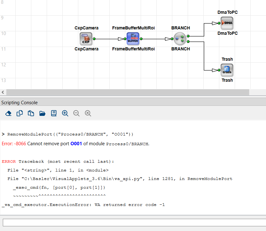
AppendModulePort#
| Command Syntax |
|---|
AppendModulePort (full_hier_box_name: str, direction: PortDirection | str) |
Command for adding an input port or an output port to a hierarchical box.
The following values for direction are available:
PortDirection.Input or "Input": an input port is created.
PortDirection.Ouput or "Ouput": an ouput port is created.
Example
AppendModulePort("Process0/MyHierBox", "Input")
Rename#
| Command Syntax |
|---|
Rename (full_module_name: str, new_name: str) |
Command for renaming a module or simulation box. In new_name you specify the new individual name of the instance without the hierarchical path.
Example
Rename("Process0/module1", "DMA")
SetActiveHierarchy#
| Command Syntax |
|---|
SetActiveHierarchy (hierarchy: str) |
Command for opening and making the specified design hierarchy window active in VisualApplets.
Example
SetActiveHierarchy("Process0/MyBox")
GetActiveHierarchy#
| Command Syntax |
|---|
| GetActiveHierarchy ( ) → str |
Returns information about the hierarchical level of the design window that is currently open and active in VisualApplets.
Example
print(GetActiveHierarchy())
Simulating the Design#
CreateSimSource#
| Command Syntax |
|---|
CreateSimSource (full_sim_module_name: str, pos: tuple[int, int] = (0,0)) → str |
Command for creating a simulation source module, and for positioning the module in the design window.
full_sim_module_name has the following syntax: <HierLevelPath>/<SimModuleName>
<HierLevelPath>defines the path to a specific hierarchical level in the design.<SimModuleName>specifies the individual name you want the simulation source module to have. Alternatively, you can leave<SimModuleName>empty. In this case, you need to terminatefull_sim_module_namewith a slash; the module will be named automatically.
The return value of function CreateSimSource is the full_module_name of the new simulation source module (full hierarchical path to the simulation source module including the module name).
Example
srcName = CreateSimSource("Process0/MySimSource", (200,200))
CreateSimProbe#
| Command Syntax |
|---|
CreateSimProbe (full_sim_module_name: str, pos: tuple[int, int] = (0,0)) → str |
Command for creating a simulation probe module, and for positioning the module in the design window.
full_sim_module_name has the following syntax: <HierLevelPath>/<SimModuleName>
<HierLevelPath>you use to define the path to a specific hierarchical level in the design.<SimModuleName>you use for specifying the name you want the simulation probe module to have. Alternatively, you can leave<SimModuleName>empty. In this case, you need to terminatefull_sim_module_namewith a slash; the module will be named automatically.
The return value of function CreateSimProbe is the full_module_name of the new simulation probe module (full hierarchical path to the simulation probe module including the module name).
DeleteSimModule#
| Command Syntax |
|---|
DeleteSimModule (full_sim_module_name: str) |
Command for deleting a simulation module (simulation source or simulation probe).
ConnectSimModule#
| Command Syntax |
|---|
ConnectSimModule (full_sim_module_name: str, link: tuple[str,str], pos: tuple[int,int] = (0,0)) |
Command for connecting a simulation module to an existing link.
Example
ConnectSimModule("Process0/MySimProbe", ("Process0/Branch1","O"))
DisconnectSimModule#
| Command Syntax |
|---|
DisconnectSimModule (full_sim_module_name: str) |
Command for detaching the simulation module from a link.
SetSimModuleProperty#
| Command Syntax |
|---|
SetSimModuleProperty (full_sim_module_name: str, prop: SimProperty|str, value: bool|int|dict[str,int]) |
Command for defining the properties of a simulation module.
- Common props (with integer as
value): "PixelAlignmentOffset","ImageFileSubPixels","ImageFilePixelBits","CurrentImage"- Common props (with Boolean as
value): "ImageFileNormalize"can be set toTrueorFalse- Common props (with dict as
value): "CropRect": pass a dict with keys:{"index", "x", "y", "width", "height"}for specifying the ROI in a source's image.
Use prop to identify the property you want to set. Set the individual properties in the format stated below. Available are the following properties and according value formats:
pixelAlignmentOffset BITS
Use this parameter to specify the alignment offset as integer value BITS.
imageFileSubPixels NUMBER
Use this parameter to specify the number of file pixels that are assigned to a link pixel as integer value NUMBER.
Source: NUMBER pixels are conflated to one pixel.
Probe: One pixel is split up into NUMBER pixels in the file.
imageFilePixelBits bits
Use this parameter to specify the bit width in the image file as integer value bits. Allowed are the values 1, 8, and 16.
imageFileNormalize choice
Use this property to configure the way simulation result images are saved.
If you want to save a 1-bit simulation result in an 8-bit file format, set imageFileNormalize to 1. "Normalizing" in this context means mapping 0 to 0 (black) and 1 to 255 (white).
The following values for choice are possible: choice = "1" | "0"
cropRect [imageNr] x y width height
This property is only available for simulation sources. Specifying the image index [imageNr] is mandatory. Use this parameter to crop an image and to specify the region of the image (ROI) you want to use for simulation. With x and y you define the left upper corner of the ROI.
currentImage index
Use this parameter to select an image within the simulation module. Specify index as integer value.
Examples
SetSimModuleProperty("Process0/SimSource1", "ImageFileNormalize", True)
SetSimModuleProperty("Process0/SimSource1", "CropRect",
                     {"index": 0, "x":10, "y":20, "width":100, "height":100})
AddImage#
| Command Syntax |
|---|
AddImage (full_sim_module_name: str, image_file_name: str|list[str], image_lib: ImageLibrary|str) |
Command for adding an image to a simulation source module. If the number of kernel elements of the link the simulation source is connected to is > 1, you must specify as many images as the kernel has elements.
Optionally, you can state the image library you want to use ( image_lib = "Native" | "ImageMagick").
Example
AddImage("Process0/MySimSource", "c:/VA_Python/testimage.tif")
RemoveImage#
| Command Syntax |
|---|
RemoveImage (full_sim_module_name: str, image_index: int = -1) |
Command for deleting one or all images from a simulation source module. Use the optional parameter image_index to specify the image you want to delete. If you set image_index to -1, or if you don't use image_index at all, all images in the simulation module are deleted.
Simulate#
| Command Syntax |
|---|
Simulate (processing_cycles: int, save_log_file_name: str) |
Command for simulating a design. Use the processing_cycles parameter for defining how many processing cycles you want to carry out with the command.
Use the optional parameter save_log_file_name to save the log of the carried-out cycles to file. Specify in save_log_file_name the path to the file and the file name itself. Use file name extension *.html, as the log is written in HTML format. Use forward slashes for indicating pathes.
Example
Simulate(1, "c:/temp/simlog.html")
ResetSimulation#
| Command Syntax |
|---|
| ResetSimulation ( ) |
Command for resetting the simulation engine. As an effect, all simulation probes in the design are cleared.
GetSimModuleProperty#
| Command Syntax |
|---|
GetSimModuleProperty (full_sim_module_name: str, prop: SimModuleProperty|str , image_index: int = -1) → varies |
Command for retrieving the properties of a simulation module. The return type depends on the queried property. The following properties are available:
IsConnected→ bool: ReturnsTrue, if simulation module is connected to a link; otherwise returnsFalse.ConnectedLink→(FullModuleName, PortName): Returns a tuple identifying the link to which the simulation module is connected to. The return value always describes the link by a real module port, i.e., it never states an inner H box node (like, for example,INBOUND#I000orOUTBOUND#O000).IsSource→ bool: ReturnsTrue, if the simulation module is aSimulationSource; otherwise returnsFalse.IsProbe→ bool: ReturnsTrue, if the simulation module is aSimulationProbe; otherwise returnsFalse.Position→(x,y): Returns position of the simulation module in the program window as a tuple.ImageCount→ int: Returns the number of images in the simulation module.PixelAligmentOffset→ int: Returns the alignment offset as integer value.ImageFileSubPixels→ bool: Returns the number of file pixels that are assigned to a link pixel as integer value.ImageFilePixelBits→ int: Returns the setting for bit width in the image file as integer value. Possible are the values 1, 8, and 16.ImageFileNormalize→ bool: ReturnsTrueorFalseaccording to the settings for saving simulation result images. If set to 1, during saving a 1-bit simulation result to a file in 8-bit *format: 0 is mapped to 0 (black) and 1 is mapped to 255 (white), i.e., the simulation image's format is "normalized".CropRect→ dict with{"x","y","width","height"}: This property is only available for simulation sources. Using parameterimage_indexis mandatory. Returns the crop rectangle as a dictionary with the keysIndex,X,Y,Width, andHeight.CurrentImage→ int: Returns the currently selected image as integer value.
SetSimImageData#
| Command Syntax |
|---|
SetSimImageData (full_sim_module_name: str, image_index: int, x: int, y: int, kernel_row: int = 0, kernel_col: int = 0, component: int = 0, width: int 0 1, data: list[str]) |
Command for overwriting one pixel or several neighboring pixels in an image within a simulation module (source or probe) in memory. This command is useful for test modifications before running the simulation or saving the simulation.
You can use this command:
- in SimSources for altering an image for simulation.
-
in SimProbes for visualizing the results within an image.
-
image_index: Which image to alter, 0-based. x,y: The top-left pixel coordinate to write to.kernel_row,kernel_col: If the image has a kernel, identify which kernel element you're modifying.component: For color images, which color channel to set.width: How many consecutive pixels in a row to set. Additional data indatacan spill onto subsequent rows.data: A list of pixel values in hex string form, e.g.["0A","0B","FF"].
Example
SetSimImageData("Process0/SimSource1", 0, 10, 10, component=0, width=3,
                data=["12","13","14"])
The alteration of the image is volatile. As soon as you select another image of the same simulation module or re-select the altered image, the altered image is loaded anew from hard disk and your alterations are discarded. You select another image if you enter a command for a new image image_index (of the same simulation module) in the Python console, or if you click another image of the same simulation module in the viewer of the VisualApplets GUI.
However, you can make your alteration permanent by saving the altered image under a new file name as long as it's active.
You can use a volatilely altered image for simulation. However, only one image per SimSource module can be used for simulation in altered condition, because altering another image in the same SimSource resets the pixel values of the image you altered before. You can use as many volatilely altered images as you want for simulation as long as you have only one volatilely altered image per simulation module.
One value per pixel: Command SetSimImageData allows you to write exactly one value per pixel. Thus, in gray scale pixels, you must carry out the SetSimImageData command only once to write the complete color information per pixel. In color pixels, you will be able to write only one of the three color components per pixel. Thus, if you want to change all three color components of color pixel(s), you have to carry out the SetSimImageData command three times.
Writing in images with kernels: When you are writing into images that have a kernel, you must specify which kernel element of the respective pixel(s) you want to overwrite when using command SetSimImageData in addition to the exact position of the (first) pixel you want to overwrite. If you want to overwrite all kernel elements, you must carry out the SetSimImageData command exactly kernel_row * kernel_col times.
To use the command:
Before using the command, close the image viewer of the simulation module the image you want to change is located in.
Specify the image you want to alter with index image_index. Attention: image_index starts with 0, whereas the numbering of the images in a simulation module in the VisualApplets GUI starts with 1. The values map as follows:
image_index = 0 referes to image 1 in the viewer of the VisualApplets GUI.
image_index = 1 referes to image 2 in the viewer of the VisualApplets GUI.
image_index = 2 referes to image 3
and so forth.
Info
On the GUI of VisualApplets, the index of the image that is used in the next simulation cycle is displayed in square brackets and marked by a preceeding "sim” (e.g., sim[2]).
Use kernel_row and kernel_col to specify the kernel element you are going to change a pixel value for.
You can see in the link properties of the link the simulation module is connected to which size the kernel of your simulation image has. A link that has a kernel size bigger than 1 pixel is always preceeded by an instance of an operator that allows specifying kernels (as, for example, operator FIRkernelNxM).
Counting kernel columns and kernel rows starts with 0. Thus, if you have a kernel with only one element, set both values (kernel_row and kernel_col) to 0:
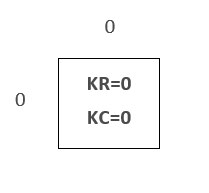
For a kernel with 4 elements, you identify an individual kernel element as follows:
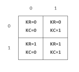
For a kernel with 9 elements, you identify an individual kernel element as follows:
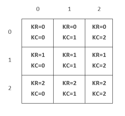
Use the component parameter to specify the color component of the pixel you want to set. In gray scale images, set component to 0. In multi-component images (color), specify the component you want to write via its position in the color model. Example: Set component to 0 if you want to address the red component in an RGB image, set component to 1 if you want to address the green component in an RGB image, or set component to 2 if you want to address the blue component in an RGB image.
Set position (x,y) to define the starting point (first pixel) for your writing within the image.
Use width to specify the number of neighboring pixels you want to overwrite per row. If you specify more values than you write pixels in a row (width), writing continues in the next row on position x. This way, you can write a region of interest (ROI) that has the width width.
Specify the individual pixel values data in hexadecimal writing without preceding "0x”. Specify negative values in two's complement notation. How many values you state in data decides how many pixels within the image are altered.
GetSimImageData#
| Command Syntax |
|---|
GetSimImageData (full_sim_module_name: str, image_index: int, x: int, y: int, kernel_row: int = 0, kernel_col: int = 0, component: int = 0, width: int = 1, height: int = 1]) |
Command for reading values of one or several neighboring pixels in an image within a simulation module (source or probe). Returns a list of hex strings.
One value per pixel: Command GetSimImageData returns exactly one value per pixel. Thus, in gray scale pixels, you must carry out the GetSimImageData command only once to retreive the complete color information per pixel. In color pixels, you will be able to retrieve only one of the three color components per pixel. Thus, if you want to read all three color components of color pixel(s), you have to carry out the GetSimImageData command three times.
Reading in images with kernels: When you are reading from images that have a kernel, you must specify which kernel element of the respective pixel(s) you want to read when using command GetSimImageData in addition to the exact position of the (first) pixel you want to read. If you want to read all kernel elements, you must carry out the GetSimImageDatacommand exactly kernel_row * kernel_col times.
To use the command:
Specify the image with index image_index.
Attention: image_index starts with 0, whereas the numbering of the images in a simulation module in the VisualApplets GUI starts with 1. The values map as follows:
image_index = 0 referes to image 1 in the viewer of the VisualApplets GUI.
image_index = 1 referes to image 2 in the viewer of the VisualApplets GUI.
image_index = 2 referes to image 3 in the viewer of the VisualApplets GUI,
and so forth.
Info
On the GUI of VisualApplets, the index of the image that is used in the next simulation cycle is displayed in square brackets and marked by a preceeding "sim” (e.g., sim[2]).
Use kernel_row and kernel_col to specify the kernel element you want to read from.
Which size the kernel of your simulation image has you can see in the link properties of the link the simulation module is connected to. A link that has a kernel size bigger than 1 element is always preceeded by an instance of an operator that allows specifying kernels (as, for example, operator FIRkernelNxM).
Counting the columns and rows of a kernel starts with 0. Thus, if you have a kernel with only one element, set both values to 0.
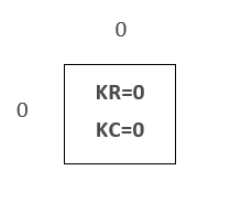
For a kernel with 4 elements, you identify an individual kernel element as follows:
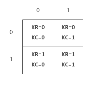
For a kernel with 9 elements, you identify an individual kernel element as follows:
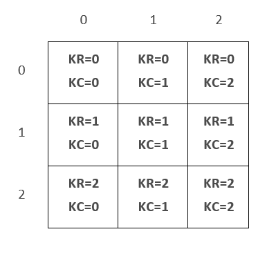
Use parameter component to specify the color component you want to read of the pixel. In gray scale images, set component to 0. In multi-component images (color), specify the component you want to read via its position in the color model. Example: Set component to 0 if you want to read the red component in an RGB image, set component to 1 if you want to read the green component in an RGB image, or set component to 2 if you want to read the blue component in an RGB image.
Set position (x,y) to define the starting point (first pixel) of your reading within the image.
If you don't use parameter Width, the value for exactly one pixel is returned. If you specify only width, width values in line y are returned. If you specify width and height, width * height values are returned. Using width and height allows you to define a region of interest (ROI) you want to read the pixel values (gray)/the values of a pixel component (color) for.
The individual pixel values are returned in hexadecimal writing without preceding "0x”. Negative values are returned in two's complement notation.
Example
vals = GetSimImageData("Process0/SimProbe1", 0, 100, 200, width=4, height=2)
# E.g., ["00","00","01","02","03","FF","7A","7B"]
CreateSimImage#
| Command Syntax |
|---|
CreateSimImage (full_sim_module_name: str, shape: tuple[int,int] = (-1,-1)) |
Command for creating / allocating a new image in a simulation module (typically a source) with the specified height and width.
If either dimension is -1, the link's maximum dimension is used.
The parameter shape defines the image shape like known for numpy arrays. The first tuple entry is height and the second is width. If shape has three entries, the third one is ignored (the number of components is determined by the link format).
Example
CreateSimImage("Process0/MySimSource", (768, 1024))
GetSimImageProperty#
| Command Syntax |
|---|
GetSimImageProperty (full_sim_module_name: str, image_index: int, prop: SimImageProperty|str, line_index: int = -1, line_count: int = 1) → varies |
Command for retrieving the properties of a simulation image (in a source or a probe module).
propcan be:"LineWidth": Returns a list of line widths (if lineCount > 1)."ImageSize": Returns a dict{"Width": <width>, "Height": <height>}where<width>and<height>are integers for the image width and height.
CreateImageMemory#
| Command Syntax |
|---|
CreateImageMemory (format_dict: dict[LinkParam|str, int|<enum>|str] = None ) → SharedImageMemory |
Command for creating a VisualApples image memory which may be accessed via an object of the type SharedImageMemory.
-
format_dict: Specifies the memory format with a dictionary equivalent to specifying link formats (using keys such asLinkParam.MaxImageWidth,LinkParam.MaxImageHeight,LinkParam.ColorFormat, etc.). If omitted, the following defaults are used:LinkParam.MaxImageHeight:1024LinkParam.MaxImageWidth:1024LinkParam.ColorFormat:VAF_GRAYLinkParam.BitWidth:8
The parameter format_dict is optional. If you want to set the image memory by calling CopySimImageData, don't provide any format. The format is then overridden by the simulation module.
Memory is allocated at the first time when one of the following actions is performed:
- Call of
CopySimImageData()for copying data from a simulation element - Call of method
data()for getting the Python buffer object fromSharedImageMemory.
This function returns a SharedImageMemory object that can be used with CopySimImageData.
The returned SharedImageMemory object provides the following class methods:
data(): Gets amemoryviewobject, which provides memory access via the Python buffer protocol without copying.shape(): Returns the shape (dimensions) of the image either as (Height,Width) for grayscale formats or (Height,Width,Components) for color images.datatype(): Returns a string representation of a numpy data type corresponding to the buffer data. This string can be used as argument of thenumpy.dtype()function for getting the numpy data type.casttype(): Returns the PEP 3118 buffer cast type of the image data. This string can be used formemoryview.cast().
Example
sharedMem = CreateImageMemory({"Max. Image Width": 100, "Max. Image Height": 100})
resultMem = CreateImageMemory({LinkParam.MaxImageWidth: 2, LinkParam.MaxImageHeight: 1, LinkParam.BitWidth: 16})

# Access the buffer sharedMem via numpy
import numpy as np

arr = np.frombuffer(sharedMem.data(0,0), dtype=np.dtype(sharedMem.datatype()))
arr = arr.reshape(sharedMem.shape())
arr[:] = 0 # initialize buffer with zeros

# Access the buffer resultMem via buffer protocol
resultData = resultMem.data(0,0).cast(resultMem.casttype())
resultData[0] = 0x1234
resultData[1] = 0x5678
CopySimImageData#
| Command Syntax |
|---|
CopySimImageData (full_sim_module_name: str, image_index: int, image_memory: SharedImageMemory, copy_to_sim_module: bool = False) |
Command for copying data to or from a simulation module to or from a SharedImageMemory buffer. By default, data is copied from the simulation module to the image memory.
- If
copy_to_sim_module=False(the default), data flows from the sim module into theimage_memory. - If
copy_to_sim_module=True, data inimage_memoryis written into the sim module's image.
Example
buf = CreateImageMemory()
CopySimImageData("Process0/SimProbe1", 0, buf)  # read data from probe
# ... do something in Python ...
CopySimImageData("Process0/SimProbe1", 0, buf, True)  # write it back
SaveImage#
| Command Syntax |
|---|
SaveImage (full_sim_module_name: str, image_index: int, image_base_name: str) |
Command for saving one or all result images from a simulation probe.
Use the mandatory parameter image_index to save a specific image out of the result images. If you want to save all images of the probe, set image_index to -1.
Use image_base_name to specify the path to the directory in your file system where you want to save the image(s), and for specifying the file name of the image file(s). Make sure the directories you specify already exist in your file system. Otherwise, you can create them using command MakeDirectoryPath.
Example: "C:/images/testimage". In the saving process, the file name extension (for example, *.tif) will be added automatically to the name.
If you save all images of the probe, an image index will be automatically added to the file name.
Example 1:
Enter
SaveImage("Process0/mySimProbe", -1, "C:/images/testimage")
to get the following files:
C:/images/testimage_0001.tif
C:/images/testimage_0002.tif
C:/images/testimage_0003.tif
…
Example 2:
Enter
SaveImage("Process0/mySimProbe", 4, "C:/images/testimage")
to get the following file:
C:/images/testimage.tif
Building the Design#
Drc#
| Command Syntax |
|---|
Drc (save_log_file_name: str = " ") |
Command for starting the first level of the Design Rule Check (DRC 1).
To get a log output, you can optionally specify the path to and the name of an html log file (*.html) in the save_log_file_name parameter.
Drc2#
| Command Syntax |
|---|
Drc2 (save_log_file_name: str = " ") |
Command for starting the second level of the Design Rule Check (DRC 2).
To get a log output, you can optionally specify the path to and the name of an html log file (*.html) in the save_log_file_name parameter.
SelectBuildConfiguration#
| Command Syntax |
|---|
SelectBuildConfiguration (config_name: str) |
Command for selecting a saved build configuration as active build configuration.
Specify the name of the desired build configuration in parameter config_name.
To get an overview over all available build configurations, enter SelectBuildConfiguration("?") - a list of the names of all available build configurations is returned. The currently selected build configuration is displayed in the first entry of the list.
Example:
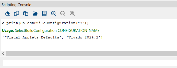
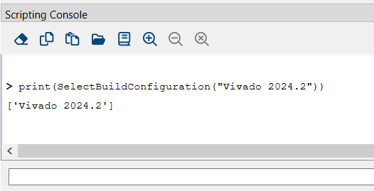
The command returns the name of the currently selected build configuration. Via this return value you can check if your re-setting the build configuration was successful.
Example:
Build#
| Command Syntax |
|---|
Build (save_log_file_name: str = " ", max_time: float | int = 24.0) |
Command for starting the build flow.
To get a log output, you can optionally specify the path to and the name of an html log file (*.html) in parameter save_log_file_name.
To set a time limit for the build process, you can optionally specify the maximum build time in parameter max_time (in hours). Parameter max_time is of type floating point. This way, you can specify fractions of an hour. The default setting for max_time is 24 hours.
Example for a command creating log file build_log.html and specifying the maximum Build time as ½ hour:
Example
Build("build_log.html", 0.5) # stop after 30 minutes
Handling Files, Paths, Program Instances and Messages#
Source#
| Command Syntax |
|---|
Source (file_path: str, encoding: str = utf-8) |
Command for executing another Python script file in the current environment. Use forward slashes for specifying the path. The command automatically replaces the following place holders (like command MakeDirectoryPath):
%UserDir%: User data directory for the current user (for example, c:/Users/Smith)
%AppDataDir%: Directory for application data of VisualApplets
%VaInstallDir%: Installation directory of VisualApplets
%UserLibDir%: Directory for user libraries.
%CustomLibDir%: Directory for custom libraries.
%VaVersion%: VisualApplets program version, for example, "3.1"
%CurrDateTime%: Current date and time according to ISO 8601 (basic format), for example "20170530T134522”
%DateTime%: Date and time at start of VisualApplets according to ISO 8601 (basic format), for example "20170530T134350”
%CurrDesignDir%: Directory in which the currently loaded design is stored.
MakeDirectoryPath#
| Command Syntax |
|---|
MakeDirectoryPath (full_path: str) → str |
Command for creating pathes (and their directories) of any desired depth.
The command automatically replaces the following place holders:
%UserDir%: User data directory for the current user (for example, c:/Users/Smith)
%AppDataDir%: Directory for application data of VisualApplets
%VaInstallDir%: Installation directory of VisualApplets
%UserLibDir%: Directory for user libraries.
%CustomLibDir%: Directory for custom libraries.
%VaVersion%: VisualApplets program version, for example, "3.1"
%CurrDateTime%: Current date and time according to ISO 8601 (basic format), for example "20170530T134522”
%DateTime%: Date and time at start of VisualApplets according to ISO 8601 (basic format), for example "20170530T134350”
%CurrDesignDir%: Directory in which the currently loaded design is stored.
If the command has been carried out successfully, the absolute path is returned.
Example
absPath = MakeDirectoryPath("c:/temp/myFolder/sub")
GetAbsolutePath#
| Command Syntax |
|---|
GetAbsolutePath (path: str) → str |
Returns the absolute path of the path you specify in parameter path.
The command automatically replaces the same alias names (place holders) as command MakeDirectoryPath.
You are allowed to refer in path to a directory or a file that doesn't exist, so that the resulting path name refers to a directory or a file that doesn't exist.
Wait#
| Command Syntax |
|---|
Wait (time_in_milli_sec: int) |
Command for waiting the specified time time_in_milli_sec. The VisualApplets GUI stays active during waiting time.
If you set time_in_milli_sec to 0, at least one event loop update of the GUI is carried out by VisualApplets. You can use this to make sure that the GUI displays the results from earlier commands.
Message#
| Command Syntax |
|---|
Message (msg_type: MessageType|str, code: int, text: str) |
Command for emitting
- an error message (
msg_type=MessageType.Errorormsg_type="Error"), - a warning (
msg_type=MessageType.Warningormsg_type="Warning"), or - an informative message (
msg_type=MessageType.Infoormsg_type="Info")
In code, you can define the message code for your message. code has the value range from -999 to +999. To avoid conflicts with the current and/or future versions of VisualAppets, use only values in this range.
Use text to enter the message. The message is completed automatically by a dot.
Example
Message("Info", 100, "Starting build steps...")
FlushConsole#
| Command Syntax |
|---|
| FlushConsole ( ) |
Transfers the accrued output from Python's stdout/stderr immediately into the VisualApplets console.
Exit#
| Command Syntax |
|---|
Exit (discard: bool = False) |
Command for terminating the current VisualApplets session. You can use Exit even if you still have a design open. However, don't forget to save your changes before.
If you still have a desing open and the design contains unsaved changes:
- If you set the optional parameter
discardtoTrue, the open design will be closed even if it containes changes that you didn't save yet. The unsaved changes will be discarded. - If you set the optional parameter
discardtoFalseand unsaved changes exist, the command will fail. - If you use
Exitwithout using thediscardparameter although the open design containes unsaved changes, the command will be terminated and you receive an according error message.