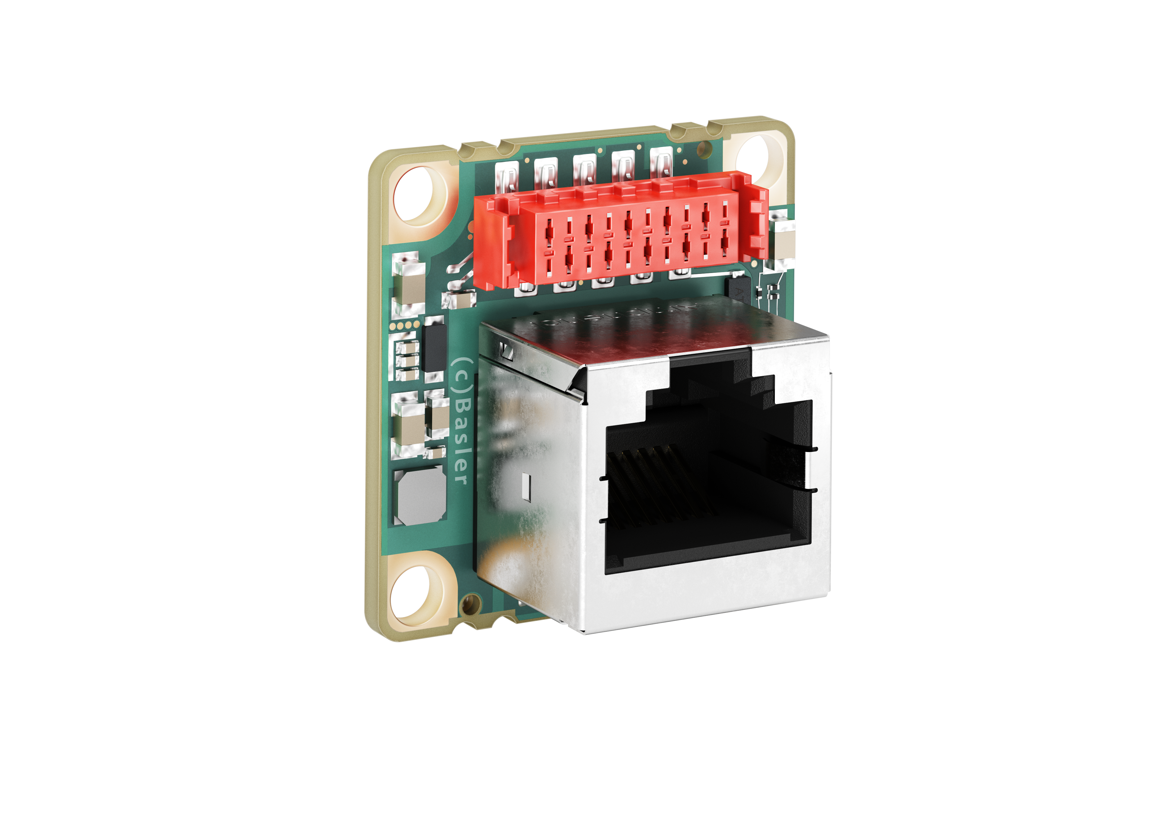
インターフェースボード dart M GigE RJ45 PoE#
仕様#
一般仕様#
| 仕様 | dart M GigE RJ45 PoE |
|---|---|
| 注文番号 | 109248 |
| I/Oライン | フォトカプラ絶縁入力ライン × 1 汎用I/O(GPIO)ライン × 1 汎用出力(GPO)ライン × 1 |
| サイズ | 27.3 x 27.3 x 25.4 mm |
| 重量 | < 12 g |
| 適合性 | CE (RoHSを含む)、EAC、KC、IEEE 802.3af (PoE) |
機械的仕様#
の寸法と取り付けポイント#
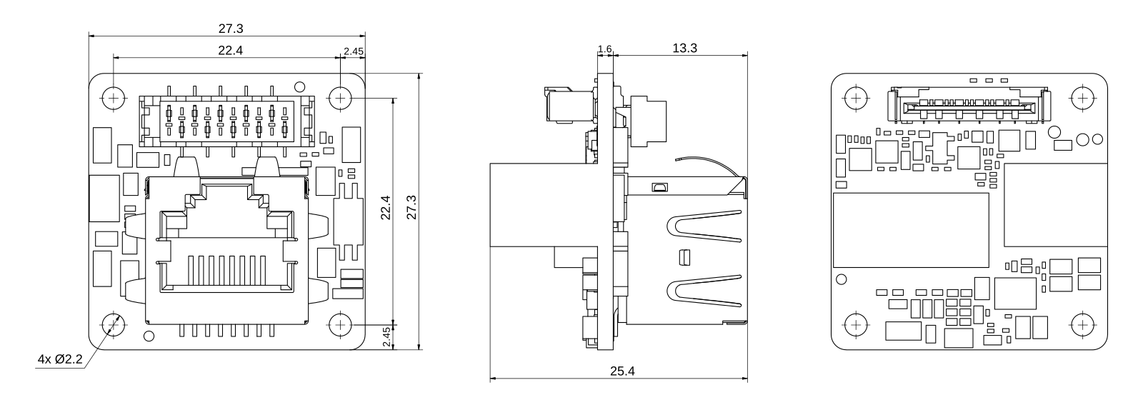
→ CAD/図面をダウンロードしてください。
注記 – イーサネットコネクタに機械的負荷がかかると、インターフェースボードが破損するおそれがあります。
イーサネットコネクタ(RJ45ジャック)に機械的負荷がかかる場合は、インターフェースボードの物理的な破損を防ぐためにケーブルのストレインリリーフを設けてください。
機械的負荷を回避する方法については、取り付け手順トピックのRJ45コネクタのストレインリリーフの確保セクションを参照してください。
要件#
電気的要件#
警告 – 感電および火災の危険
承認されていない電源装置は、感電、火災、またはその両方の原因となる場合があり、重傷や死亡につながるおそれがあります。
- 安全特別低電圧(SELV)および制限電源(LPS)またはElectrical Source 1(ES1)および電力源2(PS2)の要件を満たす電源装置を使用する必要があります。
- 電源付きハブまたは電源付きスイッチを使用する場合は、上記の要件を満たしている必要があります。
Les blocs d'alimentation non approuvés peuvent causer des décharges électriques ou des départs de feu, ou les deux. Celles-ci représentent un risque de mort ou de blessure grave.
- Vous devez utiliser un bloc d'alimentation conforme aux exigences Safety Extra Low Voltage (SELV) et Limited Power Source (LPS) ou Electrical Source 1 (ES1) et Power Source 2 (PS2).
- Si vous utilisez un hub alimenté ou un switch alimenté, ils doivent être conformes aux exigences ci-dessus.
注記 – 誤った電圧を印加すると、ボードが破損するおそれがあります。
カメラとI/O電源は、以下に示す安全動作電圧範囲内で供給する必要があります。
I/Oラインに負の電圧を使用しないでください。
カメラの出力#
GigE RJ45 PoE インターフェースボードはPower over Ethernet (PoE)をサポートしています。電源はIEEE 802.3af規格に準拠している必要があります。
電圧コンバータの効率は、2 W以上で少なくとも75%です。カメラ全体の電力要件を計算するには、カメラモジュールの電力要件をインターフェースボードの効率で割ります。
式
カメラの電力要件 = カメラモジュールの電力要件 / インターフェースボードの効率
例: 2 W / 75 % = 2.7 W
出力電力#
GigE RJ45 PoE インターフェースボードは、最大出力電力6 W向けに設計されています。この電力を超えてはなりません。
光結合I/O入力ライン#
| 電圧 | 説明 |
|---|---|
| 30VDC | 絶対最大定格。この電圧を決して超えてはなりません。超えた場合、ボードが破損し、保証が無効になることがあります。 |
| 0–24VDC | 安全動作範囲。 |
| 0~1.1 VDC | 論理0を示します(インバータは無効)。 |
| >1.1~2.2 VDC | 論理レベルの遷移が発生する領域。この領域で論理状態は定義されません。 |
| 2.2VDCより大きい | 論理1を示します(インバータは無効)。 |
- Input current (high-level): <15 mA internally limited
- 入力電流(高レベル):光カプラーの駆動には5mAより大きい電流が必要です
汎用I/Oレンズ#
注意:GPIO回線に不適切な電気信号を入力すると、ボードが重大な損傷を受けるおそれがあります。
外部回路をGPIOラインに接続する前に、Line Mode機能を使用してラインを入力または出力用に設定します。
以下に指定されたとおりに、適切な入力または出力信号電圧を印加してください。
入力として動作#
| 電圧 | 説明 |
|---|---|
| 30VDC | 絶対最大定格。この電圧を決して超えてはなりません。超えた場合、ボードが破損し、保証が無効になることがあります。 |
| 0–24VDC | 安全動作範囲。最小外部プルアップ電圧はDC 3.3V。 |
| 0–0.8VDC | 論理0を示します(インバータは無効)。 |
| 0.8–2.0VDCより大きい | 論理レベルの遷移が発生する領域。この領域で論理状態は定義されません。 |
| 2.0VDCより大きい | 論理1を示します(インバータは無効)。 |
- Input current (high-level): <100 μA
- Input current (low-level): <5 mA sink current from the GPIO input line without exceeding 0.8 VDC.
出力として動作#
| 電圧 | 説明 |
|---|---|
| 30VDC | 絶対最大定格。この電圧を決して超えてはなりません。超えた場合、ボードが破損し、保証が無効になることがあります。 |
| 3.3–24VDC | 安全動作範囲。 |
| <3.3 VDC | 信頼性の低いGPIO出力。 |
- 内部プルアップ抵抗:約650Ω(オープンコレクター)。多くのアプリケーションでは、プルアップ抵抗を追加する必要があります。
- Residual voltage ("on" state): 50mAおよび25°C(77°F)のハウジング温度で約0.4VDC。実際の残留電圧は、動作温度、負荷電流、および電子部品の生産展開に依存します。
- Leakage current: <60 µA. Actual leakage depends on operating temperature and production spread of electronic components.
- 最大負荷電流:50mA
- 最小負荷電流: :指定なし。次の点を考慮してください。
- 漏れ電流は、負荷電流が低い場合にはより強い影響を与えます。
- 負荷電流が減少すると、出力の伝播遅延が増加します。
- 高インピーダンス回路は、EMIの影響を受けやすい傾向があります。
- 電流が大きいほど、長いケーブルでの電圧降下が大きくなります。
I/Oラインの詳細については、I/O制御の項を参照してください。
汎用I/O電圧#
GPIOおよびGPOラインは、3.6 kΩのプルアップ抵抗を介してピン4に内部接続されています。回路図を参照してください。
GPOまたは出力として設定されたGPIOの出力電圧を3.3 Vより高くするには、ピン4に外部電圧を供給します。
回路図#
→「回路図」を参照してください。
ケーブル要件#
Ethernetケーブル#
- 高品質のEthernetケーブルを使用します。S/STPシールド付きのCat 5e以上のケーブルを使用することを推奨します。
- ストレート(パッチ)またはクロスオーバーEthernetケーブルのいずれかを使用してください。
- 強い磁場に近接しないようにしてください。
- Baslerは、Baslerケーブル製品ラインナップのEthernetケーブルを使用することを推奨します。
I/Oケーブル#
- I/Oケーブルの断面積は、少なくとも0.09 mm²(AWG28に近い値)が必要です。
- I/Oケーブルは電源供給には使用されません。GigE RJ45 PoE インターフェースボードはPower over Ethernet (PoE)をサポートしています。
- 最大推奨ケーブル長:10m
- 推奨コネクタ:TE 1-338095-0(圧着タイプ)またはWR-MM 690157001072(リボンタイプ)
- 強い磁場の近くでは使用しないでください。
FFCケーブル#
Baslerでは、dart Flexible Flat Cableの使用を推奨しています。
注記 – FFC ケーブルの向きを間違えると、電子回路が破損するおそれがあります。
FFCケーブルの両端に向きの指定はありません。つまり、どちらの端もカメラモジュールコネクタ、またはインターフェースボードのコネクタのどちらにでも接続できます。ただし、ケーブルを正しい向きで挿入することが重要です。つまり、次の図に示すように、FFCケーブルの赤い導電路がボード側を向いている必要があります。

物理インターフェイス#
コネクター#
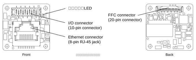
Ethernetコネクター#
- カメラへの接続:100/1000Mビット/秒Ethernet
- Power over Ethernet (PoE)
- 8ピンRJ45ジャック
注記 – イーサネットコネクタに機械的負荷がかかると、インターフェースボードが破損するおそれがあります。
イーサネットコネクタ(RJ45ジャック)に機械的負荷がかかる場合は、インターフェースボードの物理的な破損を防ぐためにケーブルのストレインリリーフを設けてください。
機械的負荷を回避する方法については、取り付け手順トピックのRJ45コネクタのストレインリリーフの確保セクションを参照してください。
I/Oコネクター#
- 10ピンメスコネクタ:WR-MM 10ピン(690367291076)。詳細については、I/O Connector Pinoutを参照してください。
FFCコネクター#
- dart Flexible Flat Cableを介してdart Mカメラへのインターフェースを提供します。
- 20ピンHirose FH67(FH67-20S-0.5SV)FFC/FPCコネクタ
ステータスLED#
カメラの動作を示します(LED点灯 = カメラ動作中)。
LEDは、次のように設定することで完全にオフにすることができます: DeviceIndicatorMode パラメータを Inactive.
LEDステータス#
| LEDステータス | 意味 |
|---|---|
| Off | 電源なし |
| 緑色で点灯 | 電源オン、ネットワーク接続確立 |
| エラーが修正されるまで緑色の点滅の繰り返し(短3回~長3回~短3回) | システムエラー(内部エラーなど) |
| エラーが修正されるまで緑色の点滅の繰り返し(長3回) | ユーザーエラー(温度エラーなど) |
| 交互:明るい緑色/消灯 | リンクダウン(電源は供給されているがGigE接続がない) |
| 交互:明るい緑色/暗い緑色 | IPアドレスの割り当て中 |
| 緑色の点灯(周期的に短時間暗くなる) | ネットワークの競合 |
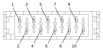
I/Oコネクタのピン配列#
| ピン | ライン | 機能 |
|---|---|---|
| 1 | - | 汎用I/O(GPIO)ライン用の接地 |
| 2 | - | 予備 |
| 3 | - | 汎用I/O(GPIO)ライン用の接地 |
| 4 | - | 外部から印加されるGPIO電圧 |
| 5 | - | 汎用I/O(GPIO)ライン用の接地 |
| 6 | ライン3 | 汎用I/O(GPIO)ラインa |
| 7 | - | 汎用I/O(GPIO)ライン用の接地 |
| 8 | ライン2 | 汎用出力(GPO)ライン |
| 9 | - | フォトカプラ絶縁I/Oラインのグランド |
| 10 | ライン1 | 光結合入力ライン |
-
BaslerのLight Control featureに対応しています。
注意事項#
→ Safety Instructions (dart)を参照してください。
インストール#
→ カメラの取り付け参照。