Flat-Field Correction (CXP Interface Cards)#
Correction methods of non-uniformities in the image caused by inhomogeneous illumination ot lenses like "shading correction" or "vignetting correction" can be compensated with a flat-field correction.
Non-uniformities in the image caused by differing light sensitivities of the sensor pixels is caused by differences of the amplifiers and ADCs of the sensor. For older CMOS sensors, this can be seen in a strong column noise.
Flat-field correction addresses three main types of non-uniformities in sensor images:
- Dark Signal Non-Uniformity (DSNU) occurs because each individual pixel can have its own offset. This effect is independent of illumination, depends on the sensor's temperature, and becomes more pronounced with longer exposure times.
- Photo Response Non-Uniformity (PRNU) is caused by variations in the gain of individual pixels, leading to differences in how they respond to light.
- Different Responses in Sensor Areas can happen when certain regions of a sensor react differently than others. These variations are typically due to the sensor's design or temperature differences across specific areas. In color cameras, this can result in noticeable color differences in certain parts of the image.
All effects can be corrected with a flat-field correction. The Enhanced Applets calculate a block-based flat-field correction. A pixel-wise or column-based flat-field correction isn't possible with the Enhanced Applets.
情報
Flat-Field Correction is also available as camera feature on some Basler cameras. If your Basler camera supports Flat-Field Correction, Basler recommends that you use the camera feature. For details, see Flat-Field Correction camera feature documentation.
The correction itself compensates for these inhomogeneities. This is done by a subtraction of the offset values followed by a gain to correct lighting response.
The block-based flat-field correction of the Enhanced Applets uses the following process:
Basler recommends not to calculate and enter the values manually into the applet. Instead, choose one of the following three options:
- Using the Flat-Field Correction Plugin for Frame Grabbers in the pylon Viewer
- Calculating Flat-Field Correction in the Framegrabber SDK
- Customizing the Flat-Field Correction Feature with VisualApplets
Using the Flat-Field Correction Plugin for Frame Grabbers in the pylon Viewer#
Basler provides a plugin in the pylon Viewer, that allows you to apply flat-field correction (FFC) to your acquisition results.
You can download the Flat-Field Correction plugin as ZIP file on the Basler Website.
システム要件#
To use the Flat-Field Correction plugin, ensure the following setup:
- A Basler camera is installed.
-
pylon 25.10 is installed on your computer.
情報
- The Flat-Field Correction plugin works only with pylon 25.10.
- If you are upgrading from pylon 8 to 25.10:
- Uninstall the old version.
- Install only the new version (pylon 25.10).
-
A frame grabber or interface card is connected to you computer.
- An enhanced applet is loaded onto your frame grabber or interface card.
Installing the FFC Plugin#
- Unzip the downloaded ZIP file.
- Locate the EnhAppletFFC.dll file. This is the FFC plugin.
- Copy the EnhAppletFFC.dll file into the pylon installation folder Applications\x64\lib\pylonviewer\plugins.

Preparation before Using the Plugin#
Before using the FFC plugin, you should review the following:
- To understand the underlying theory, see the section Background Information: Calculation Formulas.
Before calculating the correction values, ensure the following:
- Your illumination is as homogeneous as possible.
- Lens aperture and focus are correctly set.
- The exposure time is configured.
- All camera pre-processing features are configured, for example the analog gain.
- The correct Enhanced Applet is loaded.
- The correct camera pixel format is set in both the camera and the applet.
- The camera has reached its normal operating temperature.
- No pre-processing is set in the applet. Your image uses the full ROI.
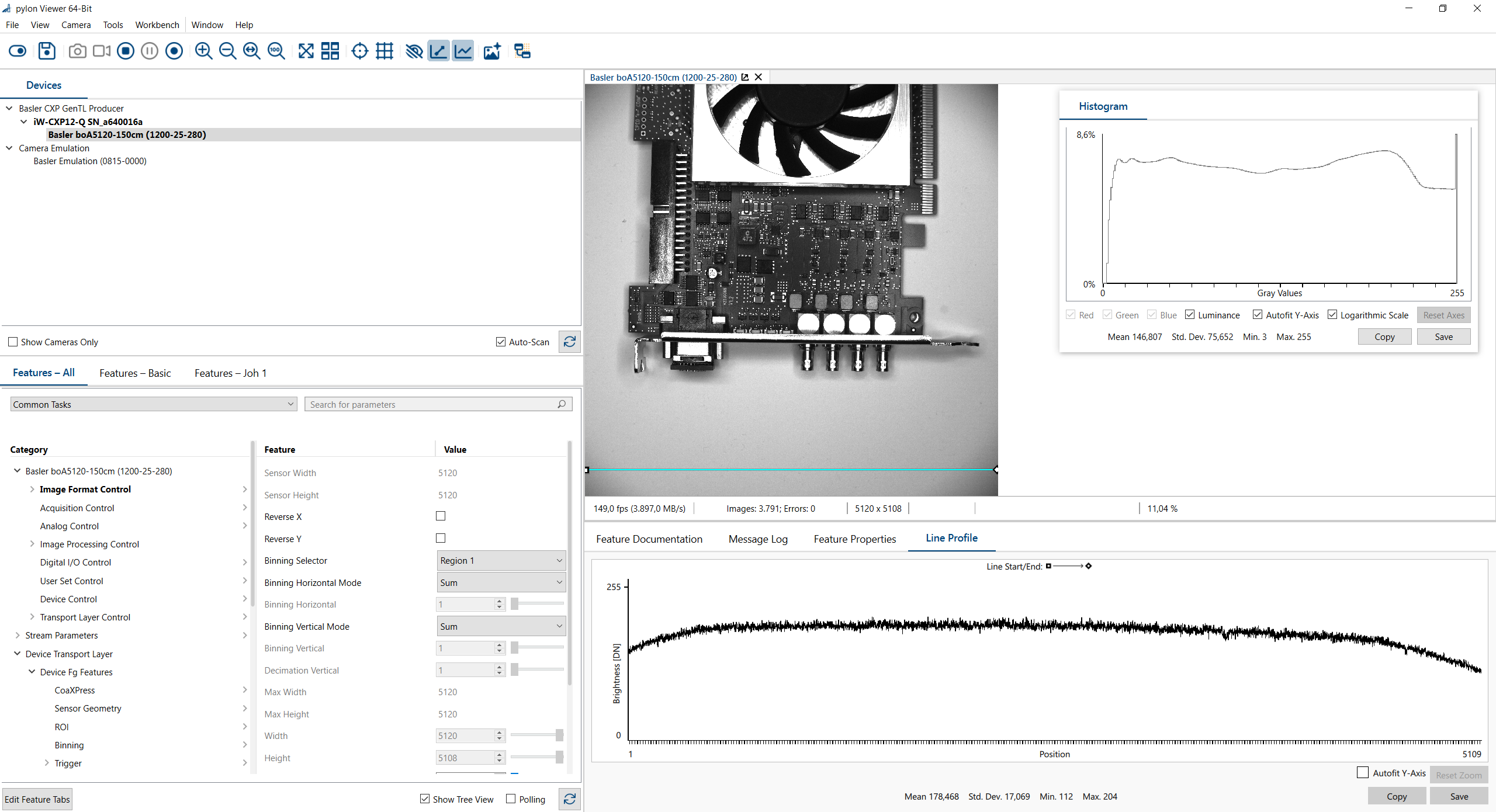
The screenshot shows the acquisition of an image in the pylon Viewer. As you can see from the line profile, there is a strong shading towards the corners of the image. Furthermore, some pixels are in saturation. This is on purpose since the darker parts of the object are the ones of interest. This is also a realistic example for machine vision applications.
Calculating and Applying Flat-Field Correction Values to Your Image#
-
Start the Flat-Field Correction plugin:
- Select a camera in the pylon Viewer.
- Stop the image acquisition of the selected camera.
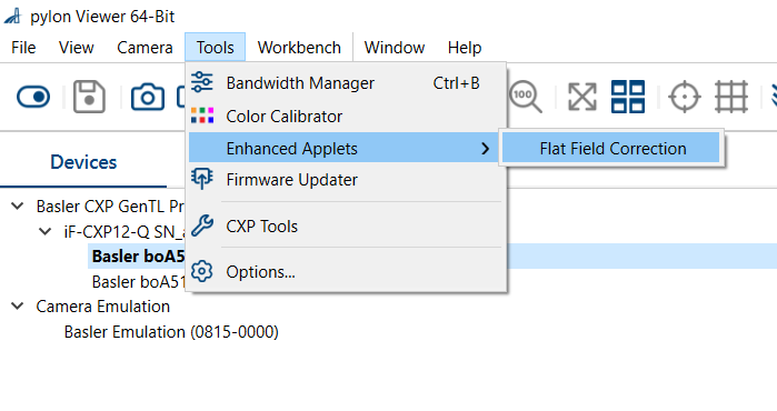
- In the pylon Viewer, select Tools > Flat-Field Correction (Frame Grabber).
-
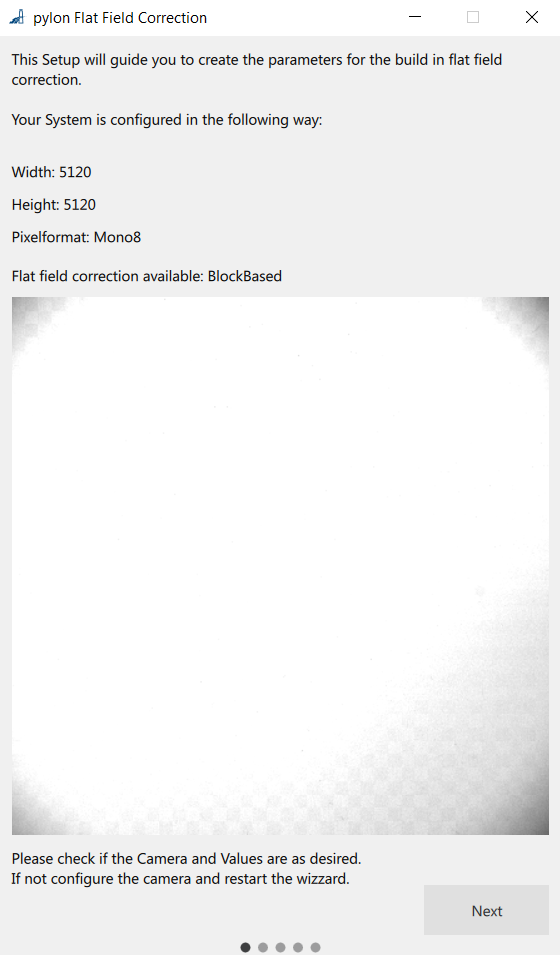
The Flat-Field Correction plugin opens:
-
In step 3. Configure the camera.:
- Configure a ROI to which the flat-field correction should be applied. If you leave the default values, the whole image will be re-calculated.
-
クリック Next.
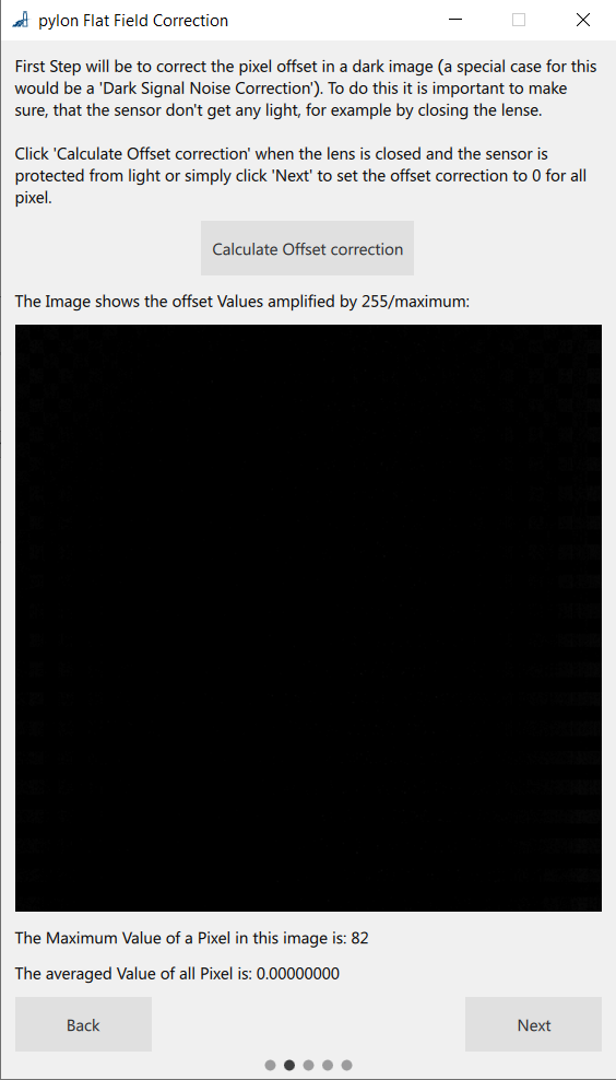
イメージ Calculate Pixel Offset (DSNU) page opens:
-
Calculate the offset correction values by acquiring a sequence of dark images. To acquire dark images:
- Cover your lens and acquire images.
- Select Calculate pixel offset.
- Click the Calculate Pixel Offset button.
The plugin displays a scaled image and the pixel offset values.
-
クリック Next.
イメージ Calculate Gain (PRNU) page opens:
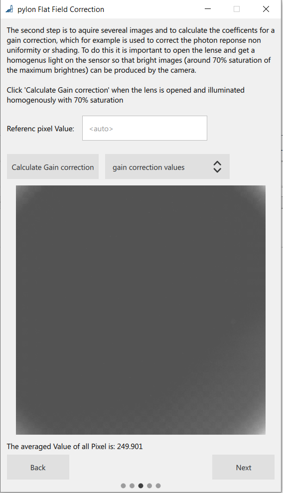
-
Calculate the gain values:
- Acquire a sequence of bright reference images to obtain the gain correction value: Place a homogenous bright object, e.g., a white sheet of paper, under the lens and acquire images.
-
Optionally, you can set a reference pixel value and exposure time.
情報
To reduce color distortions for color images, use the average gain value as the reference pixel value.
-
Click the Calculate Gain Correction button.
As a result, the gain correction values are displayed and you can see the gain-corrected image when you select Live - Gain Corrected in the View Options drop-down list box. - クリック Next.
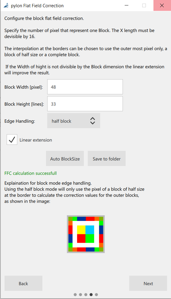
イメージ Calculate Block-Based FFC Values page opens:
-
Calculate the flat-field correction values and apply them to your image.
- Optionally, you can set the block size or do an automatic calculation. For the given example, an image size of 5120 x 5120 pixels is used, so, e.g., a block size of 48 x 34 pixels results in a total of 16157 blocks, which is less than the available total of 16384 blocks.
- Optionally, you can specify the Linear extension and set the Edge handling either to Pixel, Half Block, or Block.
- To enable the Calculate Correction Data - Store And Apply button, specify a storage location for the calculation values.
- Click the Calculate Correction Data - Store And Apply button.
- The calculation is processed, files are generated into the specified folder and the calculated gain and offset values are applied to your image.
- In the View Options drop-down list box above the image, select which FFC values shall be applied to your image in the preview: gain values, offset values, both or none.
- Click Finish to leave the FFC plugin.
-
The Line Profile now shows a homogenous image and a high-quality image can be acquired. Use the
FFC mode parameterto toggle the FFC on or off.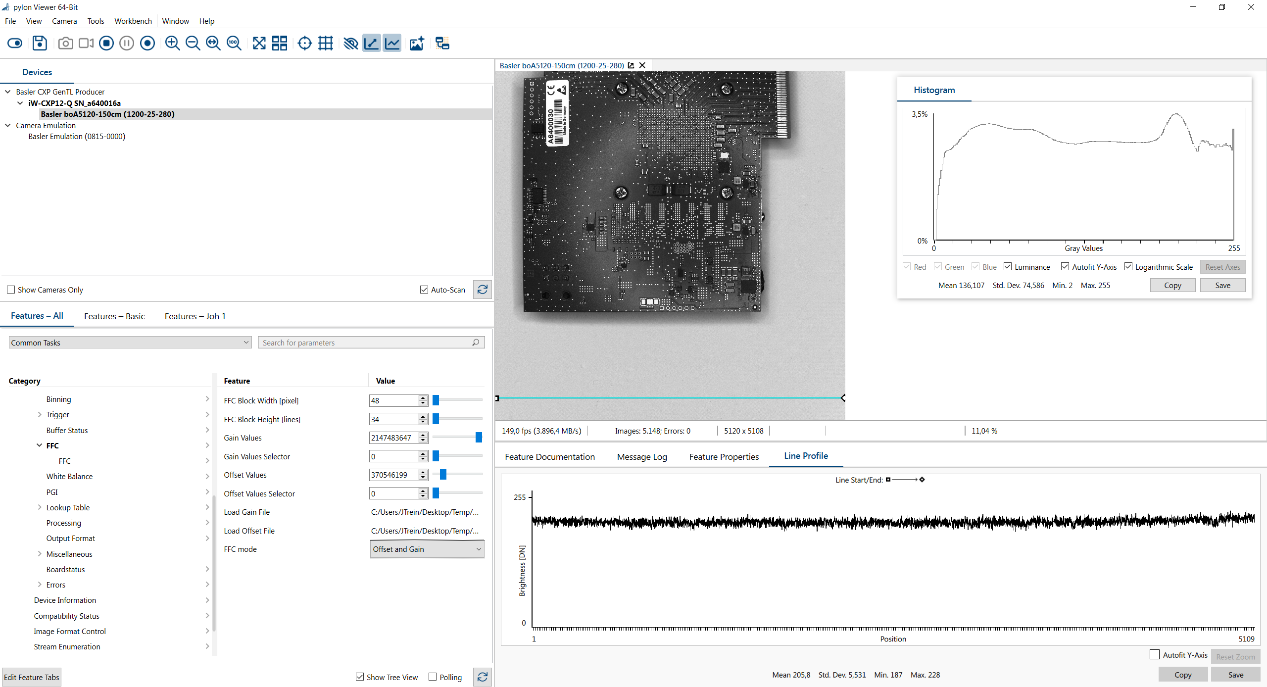
Calculating Flat-Field Correction in the Framegrabber SDK#
Basler provides Python scripts that help you calculate and apply flat-field correction values in the Framegrabber SDK.
You can download these scripts as a ZIP file from the Basler Website. The package includes:
- One script for monochrome images
- One script for color (Bayer) images
情報
Each time you restart your computer or open the frame grabber application, the FFC settings must be re-loaded to the frame grabber. A frame grabber has a volatile memory, so no data can be stored as opposed to the camera user sets on the cameras.
To calculate flat-field correction values, adapt the python script to your image paths and parameters:
- Acquire a dark image:
- Cover your lens and capture a dark image.
- Save the image to your computer.
- Acquire a bright reference image (for gain correction):
- Place a uniform bright object (e.g., a white sheet of paper) under the lens and capture an image.
- Save the image to your computer.
-
Edit the Python script:
- Open the script in a text editor.
-
Update the paths to your dark and bright images in the specified section:
################# Calculation of pixelwise FFC coefficients for offset and gain########################## # Read dark image # Set the image path darkImage = cv2.imread("C:/.../examples/Processing/Shading/Shading2D/ImagesBlockFFC/darkImage_5120x5120_bayerBG8.bmp",-1) # Read bright image # Set the image path brightImage = cv2.imread("C:/.../examples/Processing/Shading/Shading2D/ImagesBlockFFC/brightImage_5120x5120_bayerBG8.bmp",-1) -
For color images, also adapt the Bayer pattern directly underneath the image paths:
-
Adapt the following parameters in the
# set parameters:section:You can obtain these parameter values from your enhanced applet or VisualApplets design. To access the applet, open it in one of the following tools:# set parameters: MaxNumberOfBlocksInY = 16384 MaxNumberOfBlocksInX = 3072 blocksize_x = 64 blocksize_y = 64 offsetBits = 8 # "Offset Bits must be more than the fractional bits in it!" offsetFractionalBits = 2 gainBits = 12 #"Gain Bits must be more than the fractional bits in it!" gainFractionalBits = 10 parallelism=16 w = 5120- microDisplay X
- pylon Viewer
- VisualApplets
-
Save your changes and run the Python script.
- The script creates *.txt files containing the gain and offset values required for flat-field correction. These files are saved in the same directory as the Python script.
To apply the gain and offset values:
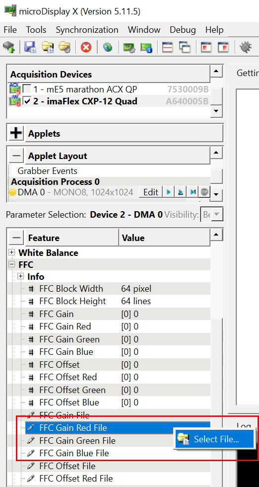
- Open microDisplay X and load the Enhanced Applet.
-
ペインの
FFCparameter block, load the offset and gain values from the files you generated:
-
Navigate to the directory where the gain and offset files are stored and select the appropriate file.
- Repeat this step for both gain and offset files and for each color channel in your image.
- 画像取得を開始します。
-
In the
FFC Modeparameter, selectOffset and Gainto apply the values: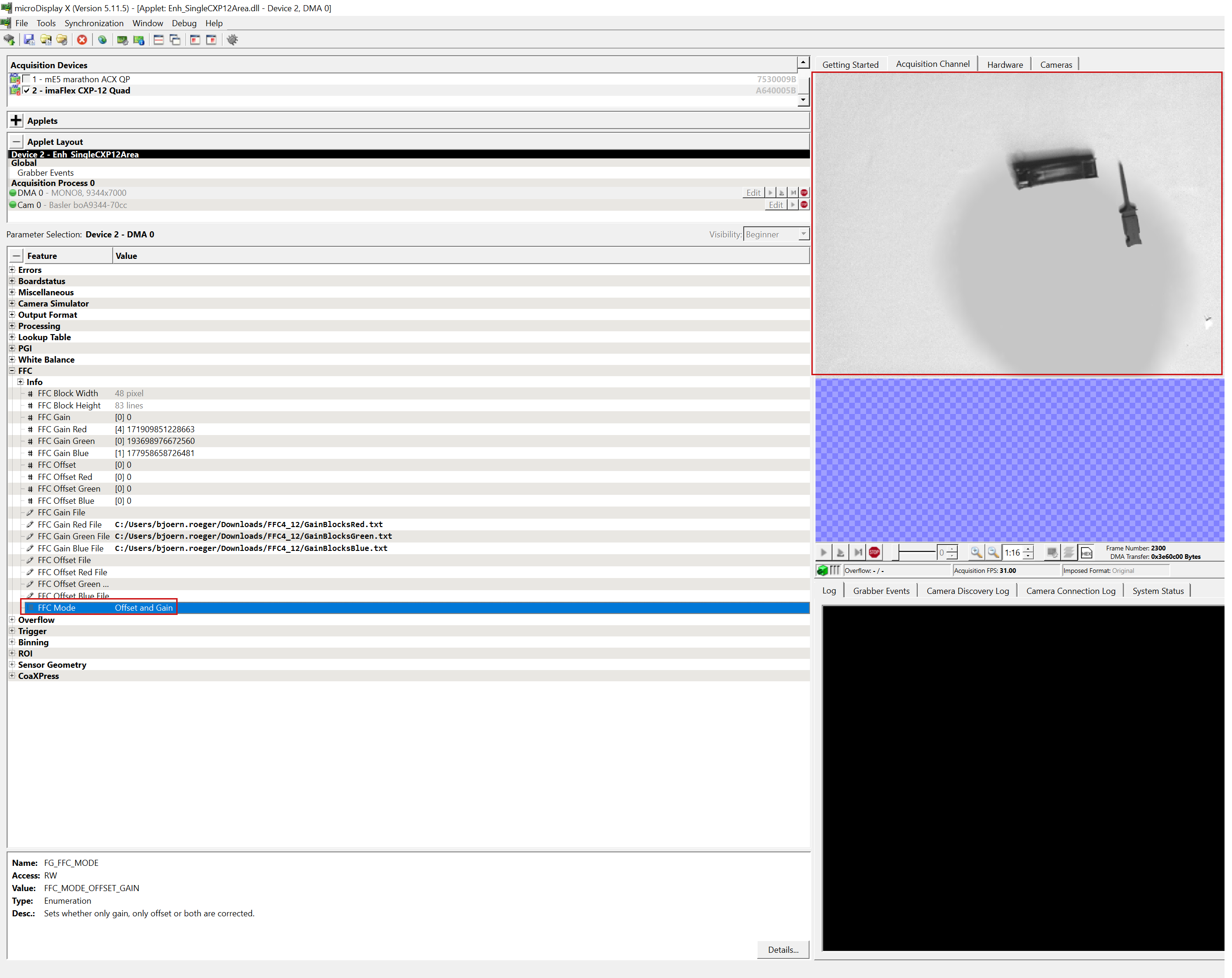
Flat-field correction is now applied to your acquired images.
Customizing the Flat-Field Correction Feature with VisualApplets#
VisualApplets includes design examples for calculating block-based flat-field correction. Use these examples if you need to adapt the functionality to your application instead of using the standard implementation in the Enhanced Applets. For details and storage locations, see the VisualApplets Tutorial.
Using the example in VisualApplets is similar to using the Enhanced Applets. Follow these steps:
- Calculate the coefficients using the Enhanced Applets and the provided Python script as described in Calculating Flat-Field Correction in the Framegrabber SDK.
- Open a flat-field correction example design in VisualApplets.
-
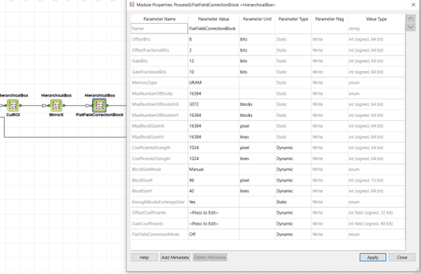
Configure the static parameters of the FFC hierarchical box in VisualApplets.
The hierarchical box automatically adapts to the pixel bit width, parallelism and image format. First, you must parameterize the input link. It's important to do this before setting the static parameters.
Allowed formats are:
Bit width: 8 to 16Artithmetic: unsignedParallelism: 1 to 64Kernel Columns,Kernel Rows: 1Color Format: VAF_GRAYColor Flavor: FL_NONEMax. Image Width: anyMax. Image Height: any
The static parameters define the precision and FPGA resource usage of the block-based FFC:
OffsetBits: Defines the number of bits used for offset correction. This is the sum of the integer and fractional bits.OffsetFractionalBits: Defines the number of fractional bits. For fixed point arithmetic explanation see section Loading of the Correction Coefficients Offset and Gain.GainBits: Defines the number of bits used for gain correction. This is the sum of the integer and fractional bits.GainFractionalBits: Defines the number of fractional bits. For fixed point arithmetic explanation, see section Loading of the Correction Coefficients Offset and Gain.MemoryType: Select either UltraRAM, Block RAM, or LUT RAM. UltraRAM is recommended.MaxNumbrOfBlocks: Select the maximum number of blocks used for the block-based FFC. If you have selected URAM asMemoryType, only 16384 blocks can be used.MaxNumberOfBlocksInX: Define the maximum number of blocks in X-direction. Usually this should beMax. Image Width/Parallelism.MaxNumberOfBlocksInY: Define the maximum number of blocks in Y-direction.MaxBlockSizeInX: Define the maximum block size in X-direction. Choose a suitable value for your application. For a general purpose use, you can set the full image width.MaxBlockSizeInY: Define the maximum block size in Y-direction. Choose a suitable value for your application. For a general purpose use, you can set the full image height.
The dynamic parameters can be changed during runtime to the application requirements:
CoefficientsXLength: This value needs to match to the calculated and uploaded coefficient files, e.g., the ROI size of the Enhanced Applet which you have used in the pylon Viewer and the FFC plugin.CoefficientsYLength: This value needs to match to the calculated and uploaded coefficient files, e.g., the ROI size of the Enhanced Applet which you have used in the pylon Viewer and the FFC plugin.BlockSizeMode: Select手動またはAuto. In auto mode, the available blocks will be distributed over the image. For manual mode, the following parameters can be used to set the block size. If you used the FFC plugin in the pylon Viewer, copy the corresponding values:BlockSizeInX: Define the block size ifBlockSizeModeis set toManual. If you used the FFC plugin in the pylon Viewer, copy the corresponding values to this parameter.BlockSizeInY: Define the block size ifBlockSizeModeis set toManual. If you used the FFC plugin in pylonViewer, copy the corresponding values to this parameter.EnoughBlocksForImageSize: This read-only parameter indicates whether the defined maximum number of blocks are enough for the given block size and ROI setting.OffsetCoefficients: Is a field parameter for the offset coefficients. Upload the text file from the FFC pylon plugin. You find a description of the format in section Loading of the Correction Coefficients Offset and Gain.GainCoefficients: Is a field parameter for the offset coefficients. Upload the text file from the FFC pylon plugin. You find a description of the format in section Loading of the Correction Coefficients Offset and Gain.FlatFieldCorrectionMode: Select, if you want the FFC Offset and Gain on or off. This can be done during image acquisition.
-
Configure the dynamic parameters of the FFC hierarchical box either during design time in VisualApplets or during runtime with your SDK application (pylon API, GenApi, GenTL consumer or Framegrabber SDK).
The following screenshot shows the use of the FFC hierarchical box in VisualApplets together with the parameters.
Background Information: Calculation Formulas#
The following sections explain the formulas used to calculate FFC values. This information is provided for reference only.
情報
Basler strongly recommends not calculating these values manually or entering them manually into pylon or microDisplay X, as this can lead to errors. Instead, use the provided scripts and plugins.
Determine Offset and Gain Coefficients#
Before calculation of the correction values some preparation is required.
- Your illumination should be as homogeneous as possible.
- Lens aperture and focus should be correctly set.
- The exposure time needs to be configured as well.
- All pre-processing features in the camera, such as analog gain, etc., need to be configured.
- The camera should run at normal operating temperature.
Offset#
Calculating the offset coefficients for the correction follows a standard way with some individual deviations which is explained in this section.
To determine the offset coefficients to correct the DSNU or any sensor-related offsets, you must acquire a camera image where the sensor doesn't get any light, e.g., with lens cap closed. In theory, the sensor should output all zero values, however, due to DSNU, the pixel values can have individual offsets. Thus, the acquired dark image represents the offset field, i.e., the offset coefficients.
As DSNU varies with the camera settings and the temperature, you should acquire the images under real conditions, especially regarding exposure and analog gain settings. Moreover, the offset values should be derived from the mean value of multiple images to eliminate the noise.
D(x, y): average dark pixel value over several images at position x,yOffset(x, y)=D(x, y)
Gain#
The acquired objects in your application have different brightness values. You must identify the brightest parts in your image, e.g., white or reflective parts. The exposure, aperture and lighting should be set so that these parts are close but not in saturation. (Unless you want to, because you are interested in dark parts only).
For example, you want to investigate bright objects on a dark background. In this case put the object in front of the lens under real exhibition conditions. The brightest spot of the investigated object should be close, but not in saturation. For example, for 8-bit images, aim for a pixel value around 240. Next, you need to illuminate the sensor homogenously with an object close to the same brightness value. For example, this could be a white paper without any structures. Again, none of the pixels should be in saturation. Record some of these reference images and calculate an average image P(x,y).
Next, several methods exist to derive the reference pixel value for the gain correction.
-
Mean value in reference image: If the brightest parts in
P(x,y)are equal to the brightest parts of the acquired objects. Thus, you can use the mean pixel value ofP(x,y)as a reference.PMean=Mean(P(x,y)).The gain coefficients will then be:
$$ Gain(x,y) = \frac{PMean}{(P(x,y)-Offset(x,y))} $$
-
User-defined reference value or brightest spot: If the mean brightness in your reference image is not equal to the desired maximum pixel values, you can define a reference value by yourself. This could be the value of the brightest spot in your image or the difference between your reference object and reference bright image. The gain values will then be calculated so that the pixels of the homogenous images are corrected to this reference value
PRef.$$ Gain(x,y) = \frac{PRef}{(P(x,y)-Offset(x,y))} $$
In both formulas, the previously determined offset is subtracted prior to the division. This must not be done, if P(x,y) is already corrected by the offset in a two-step procedure.
FFC for Bayer Pixel Format#
For the Bayer pixel format, the FFC is processed on the RAW Bayer images before converting them to RGB or any other color space. This gives a maximum precision. Calculating the correction coefficients is done individually for each color component. As a side effect, the FFC also does the color calibration as the reference image is corrected to a perfect white image.
Definition of Block-Based Flat-Field Correction#
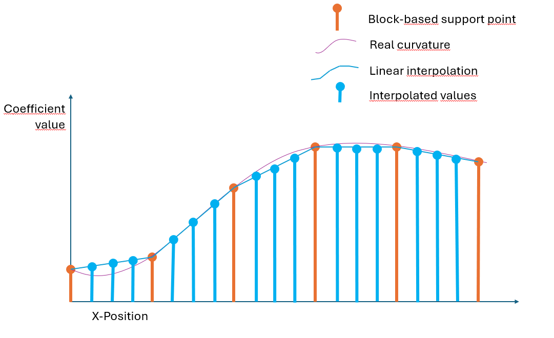
The block-based flat-field correction is used when there isn't enough memory to store a correction value for each individual pixel. In that case, the image is split into blocks whose sizes you can define. Each block has its own starting offset and gain coefficient at the corners.
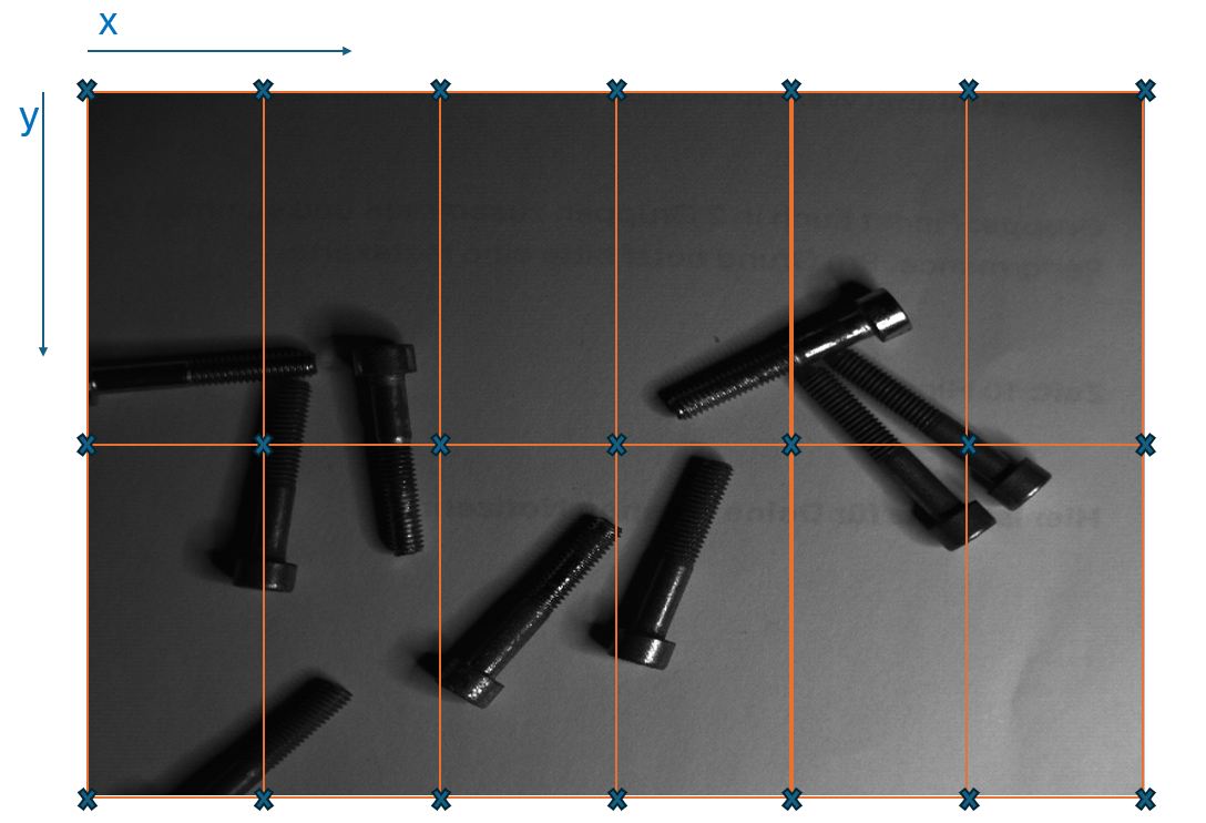
For all pixels in-between, the coefficients are determined using linear interpolation inside the frame grabber.
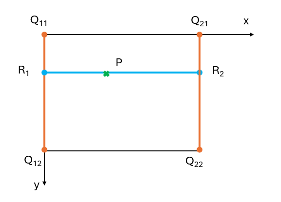
This results in a very precise correction, but it can't correct individual pixels especially for DSNU and PRNU caused by individual pixel variations.
Manual Calculation of the Block Size and Applet Parameter Values#
To use the block-based FFC in the applet, you must perform two steps after the correction values have been calculated:
- Configure the block size.
- Load the correction coefficients onto the frame grabber.
Configuring the Block Size#
As you can connect any camera with different resolutions to the frame grabber, the applet implementation is made to adapt to different resolutions.
All blocks have the same size, but they don't need to be squares, i.e., height and width might differ. The frame grabber offers a total of 16384 blocks for Offset and Gain correction values. Thus, you must adapt the block so that the blocks can be distributed to the image size.
Example: The boost V boA5120-230cm has a resolution of 5120 x 4096 pixels. If you want to use the full resolution, you must distribute the available 16384 blocks to all these blocks.
The blocks don't necessarily need to be square-shaped. Maybe your shading is stronger in X- than in Y-direction, so you should have a smaller block size in X- and a larger block size in Y-direction.
The following image shows non-squared blocks, where the resolution in X-direction is higher than in Y-direction:

To equally distribute the 16384 blocks as square blocks over the whole image, use the following formulas.
- Image width:
W - Image height:
H - Total number of blocks:
N
The total area of the image is: Image Area = W x H
Each block is square with a side length s. The area of one block is: Block Area = s2
The number of blocks is:
$$ N = \frac{Image\space Area}{Block\space Area} = \frac{W\times H}{s^2} $$
To find s:
$$ s = \sqrt{\frac{W\times H}{N}} $$
For the example above: W = 5120, H = 4096, N = 16384:
$$ s = \sqrt{\frac{5120\times 4096}{16384}} = \sqrt{1280} = 35.78\space pixels $$
Not every block side length can be configured in the applets. For example, the block size in X-direction needs to be a multiple of 16.
For the given example, the block size is rounded down to Bx= 32.
To calculate the block height, you need to consider non-squared blocks to fully use the available blocks:
s2 = block size in X x block size in Y = Bx x By
The block height can then be determined as:
$$ B_y=\left \lceil\frac{W\times H}{N\times B_x}\right \rceil $$
For the example above, this will be:
$$ B_y=\left \lceil\frac{5120 \times 4096}{16384 \times 32}\right \rceil = 40 \space pixels $$
The actual used number of blocks will then be:
$$ N_{actual}= \left \lceil\frac{W}{B_x}\right \rceil \times \left \lceil\frac{H}{B_y}\right \rceil = 16384\space blocks $$
You can now set the applet parameters:
FlatFieldCorrectionBlockWidth= 32FlatFieldCorrectionBlockHeight= 40

Loading the Correction Coefficients Offset and Gain#
Each block requires a set of four offset and gain coefficient values Q11,Q12,Q21,Q22. Those values are the support-positions at the edges of the block.

The end position of a block is the starting position of the next block. So Q11,Q12 of a current block is equal to Q21,Q22 of the next horizontal block.
The following example shows a block size of 4x3 at an image of size 8x6. It's obvious that the end-positions overlap with the start-positions of the next block. Moreover, the block end support positions at the image edge are outside the image boundaries. If the block size isn't an integer divisor of the image size, the blocks at the image edge will be even further outside of the image.
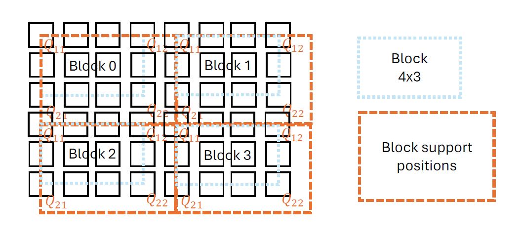
- Block 0
- Q11 at x = 0, y = 0
- Q12 at x = 4, y = 0
- Q21 at x = 0, y = 3
- Q22 at x = 4, y = 3
- ブロック1
- Q11 at x = 4, y = 0
- Q12 at x = 8, y = 0
- Q21 at x = 4, y = 3
- Q22 at x = 6, y = 3
- ブロック2
- Q11 at x = 0, y = 3
- Q12 at x = 4, y = 3
- Q21 at x = 0, y = 6
- Q22 at x = 4, y = 6
- ブロック1
- Q11 at x = 4, y = 3
- Q12 at x = 8, y = 3
- Q21 at x = 4, y = 6
- Q22 at x = 6, y = 6
The values for Offset and Gain are represented as fixed point values with a specific range and resolution. The applet has some info parameters to check the range.
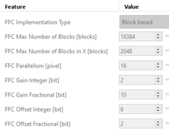
For the given example, the Gain values have the following range:
$$ \left [0,2^{GainInteger} - \frac{1}{2^{GainFractional}}\right ] = \left [0,2^{2} - \frac{1}{2^{10}} \right ] = \left [0, \space 3.999\right ] $$
In other words, the applet allows gain corrections up to 3.999. For example, a pixel value of 50 could be corrected at maximum to 50 x 3.999 = 199.
To convert a float value into a fixed point value, multiply it with the fractional bits and limit it to the ranges [0,2GainBits - 1], where GainBits = GainInteger + GainFractional.
$$ Gain_{FixedPoint} = Gain_{Float} \times 2^{GainFractional} $$
The fixed- point values Q11,Q12,Q21,Q22 are appended to a large integer value for each block.
$$ Block(i) = Qfix_{11}\times 2^0 + Qfix_{12} \times 2^{GainBits} + Qfix_{21} \times 2^{2\times GainBits} + Qfix_{22} \times 2^{3\times GainBits} $$
Or as a bit shift operation:
$$ Block(i) = Qfix_{11} + Qfix_{12} \ll GainBits + Qfix_{21} \ll 2\times GainBits + Qfix_{22} \ll 3\times GainBits $$
For example, float values:
$$ Q_{11} = 1.1, Q_{12} = 1.3, Q_{21} = 0.9, Q_{22} = 1.4 $$
are converted to fixed-point using the resolution above to
$$ Q_{11} = 1126, Q_{12} = 1331, Q_{21} = 922, Q_{22} = 1433 $$
The applet value becomes
$$ Q_{11} = 1126, Q_{12} = 1331, Q_{21} = 922, Q_{22} = 1433 $$
Hence the applet parameter value becomes
$$ Block(i) = 1126 + 1331 \ll 12 + 922 \ll 2\times 12 + 1433 \ll 3\times 12 = 98490484208742 $$
In hexadecimal representation:
$$ Block(i) = 0\times 466 + 0\times 533 \ll 12 +0\times 39A \ll 2\times 12 + 0\times 599 \ll 3\times 12 = 0\times 599\space 39A\space 533\space 466 $$