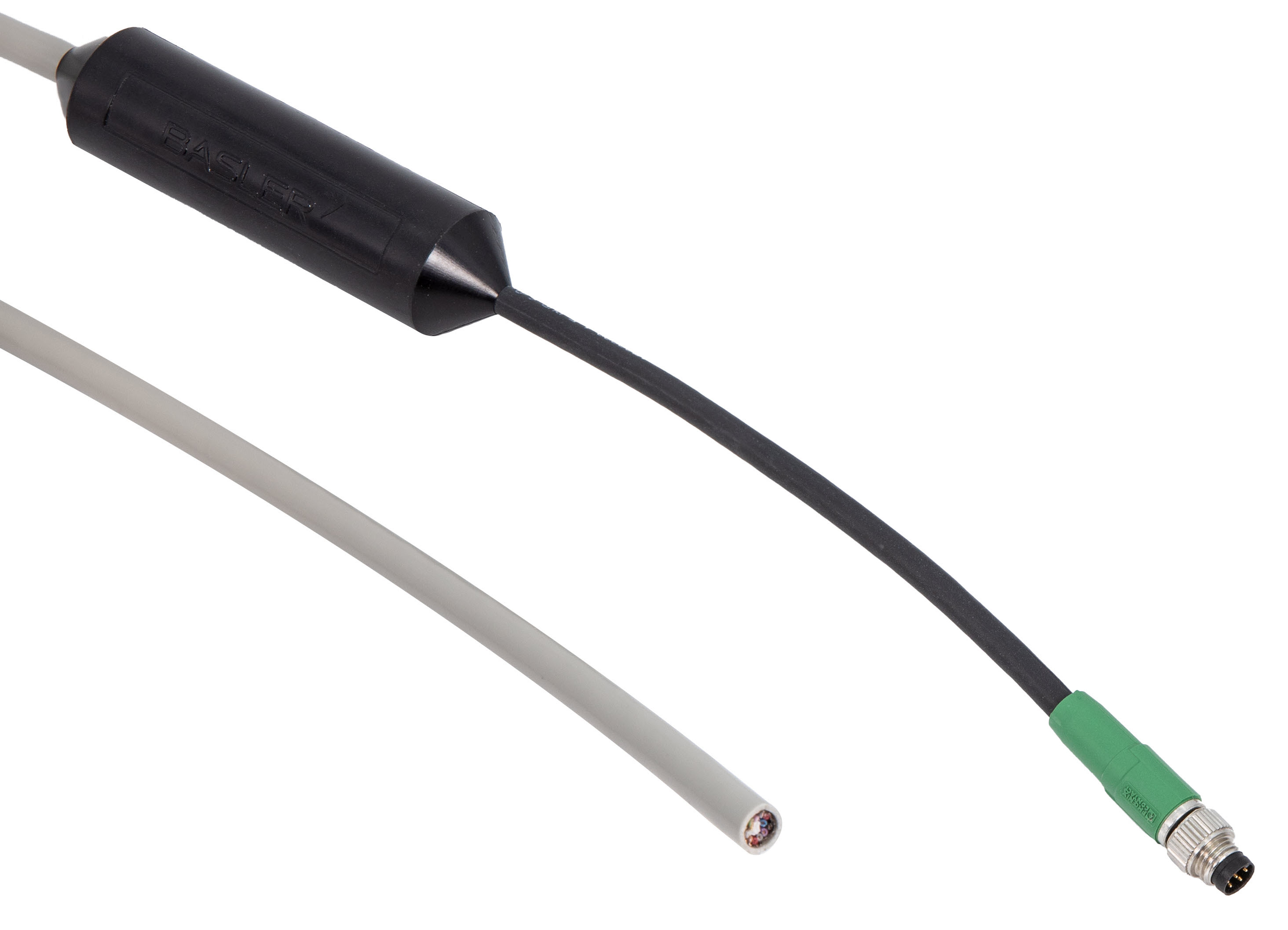
Basler Power-I/O Cable RS-422 M8 6p/open#

はじめに#
The Power-I/O RS-422 cables feature an M8 6-pin connector (camera side) and an integrated signal converter.
The key feature of this board is that it is able to convert RS-422-differential signals to single-ended signals compatible with the GPIO and opto-coupled input ports of a Basler ace 2 or racer 2 S camera.
In addition to RS-422, the signal converter for input line 1 accepts 5 V TLL and 24 V PLC signal levels via separate wires.
技術データ#
情報
The cable is suitable for the following camera models: Basler ace 2 or Basler racer 2 S cameras.
| 注文番号 | ケーブル長 |
|---|---|
| 2200002274 | 10 m |
ケーブル図面#
CAUTION – Fire hazard may cause burns or damage the camera.
The cable is designed for a total current of 1 A or less. Exceeding this limit can present a fire hazard and a risk of personal injury due to overheating. Basler recommends using a fuse or a limited power supply to ensure staying within the safe operating limits.
CAUTION – Using unsuitable cameras may damage components.
The Power-I/O Cable RS-422 M8 6p/open was specially designed for use with a Basler ace 2 or a Basler racer 2 S camera. If you use the cable in combination with other camera models, even if the connector fits, this can damage the signal converter circuit, the cable, or the camera.
配線情報#
| オープンエンド | ワイヤーの色 | Function in Camera | Port Type in Camera |
|---|---|---|---|
| VCC In (12V-24V) | 茶色 | AUX power power supply | Power |
| GND | White | グラウンド | Power GND |
| TTL In | イエロー | Input line 1 (opto-coupled) | Opto In |
| GND | 緑 | グラウンド | I/O GND |
| PLC In | ピンク | Input line 1 (opto-coupled) | Opto In |
| GND | グレー | グラウンド | I/O GND |
| RS-422_n (1) | グレー/ピンク | Input line 1 (opto-coupled) | Opto In |
| RS-422_p (1) | 赤/青 | Input line 1 (opto-coupled) | Opto In |
| RS-422_n (2) | 青 | Input line 2 | GPIO |
| RS-422_p (2) | 赤 | Input line 2 | GPIO |
| RS-422_n (3) | 紫 | Input line 3 | GPIO |
| RS-422_p (3) | Black | Input line 3 | GPIO |
情報
- Due to the integrated opto-coupler, input line 1 offers only limited speed. If you require high speeds in your applications, Basler recommends using input line 2 or input line 3 for external triggering. Details:
- TTL In, PLC In, and RS-422 (1) drive an opto-isolated low-speed camera input.
They are best suited for signals with a switching frequency of 10 kHz or less. - RS-422 (2) and RS-422 (3) are for general-purpose full-speed inputs.
- TTL In, PLC In, and RS-422 (1) drive an opto-isolated low-speed camera input.
- Each of the wires for VCC, TTL In, and PLC In is twisted with a corresponding GND wire.
For best immunity against electromagnetic fields, all GND wires should have a low-impedance connection to the same GND point. - The signal converter is powered via VCC. VCC must therefore be connected to a power source, even if the camera is powered via Power over Ethernet (PoE) or Power over CoaXPress (PoCXP).
- TTL In, PLC In, and RS-422 (1) are connected in a 'wired-or' configuration. Unused signals must be left unconnected. TTL In and PLC In can optionally be connected to GND for best immunity against electromagnetic interference.
- To protect the signal converter from damage in case of a short circuit, Basler recommends using a VCC voltage of 12 V.
However, it is safe to operate the converter cable and camera with a VCC voltage of 24 V.
物理的仕様#
| カメラ側コネクター | M8 6ピン、オスプラグ、標準コーディング |
| ホスト側コネクター | なし、オープンエンド |
| ケーブル断面積 | 6 x 2 x 0.14mm²(AWG26付近) |
| ケーブル直径 | 7.1 mm |
| ワイヤー絶縁 | PVC |
| アウタージャケット | PVC |
| 最小曲げ半径 | 42.6mm(6 xケーブル径)、固定設置 |
| 最大曲げサイクル | なし(固定設置のみ) |
| ドラッグチェーン用途に最適 | いいえ |
| ロボティクス用途に最適 | いいえ |
電気仕様#
| 公称動作電圧 | お使いのカメラの電源要件については、カメラのドキュメントを参照してください。 |
| 最大動作電圧 | お使いのカメラの電源要件については、カメラのドキュメントを参照してください。 |
| ワイヤー抵抗 | 142Ω/km以下 |
DC Characteristics#
The following table shows the DC (direct current) characteristics.
| 説明 | RS-422 | TTL 5 VDC | PLC 24 VDC |
|---|---|---|---|
| Minimum Input Voltage | -7 VDC | 0 VDC | 0 VDC |
| Nominal Maximum Input Voltage | 12 VDC | 24 VDC | 24 VDC |
| Absolute Maximum Input Voltage | 14 VDC | 30 VDC | 30 VDC |
| Maximum Low-level Voltage Threshold | -200 mV diff | 1.4 VDC | 8.4 VDC |
| Minimum High-level Voltage Threshold | 200 mV diff | 2.6 VDC | 10.8 VDC |
注意 – 電圧が指定範囲から外れると、カメラが損傷するおそれがあります。
The absolute maximum input voltage of 30 VDC must never be exceeded, not even for a short time. Doing so may damage the camera and voids the warranty.
情報
- The threshold voltages for TTL In and PLC In reflect the camera's threshold voltages, which are increased by the forward voltage of the Schottky diodes in the 'wired-or' circuit.
- RS-422 threshold voltages refer to the differential voltage between RS-422_p (X) and RS-422_n (X), with 'X' for the input line.
環境仕様#
| 動作温度範囲 | -25~80°C(動作なし) |
プラグの仕様#
| 接触めっき | Ni/Au |
| 保護等級 | IP67(ロックされた位置) |
概要#
| 適合性 | CE(RoHSを含む) お使いのケーブルの証明書 詳細については、Baslerウェブサイトの「Compliance」セクションを参照してください。 |
| 保証 | 3年 |
Read the topic about your camera model before connecting the cable to the camera. You can find your camera topic in the Area and Line Scan Cameras section under "Models".