Configuring a Single-Ended Line Trigger with CXP-12 Interface Card and a Basler racer 2 CXP Camera#
These instructions are for any racer 2 CXP camera, i.e. racer 2 L and the racer 2 S CXP cameras.
Hardware Setup When Using the Front GPIO Connection#
Wiring#
When using a single-ended signal, you must use four pins of the front GPIO.
The setup can look like this:
In addition, the trigger input block of the frame grabber actually needs a reference voltage. This voltage either comes from your circuit via
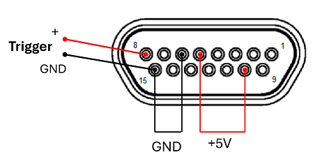
Alternatively, when using +5V TTL, this supply can be obtained from the frame grabber itself by connecting
- Pin 5 and Pin 10 (+5V) and
- Pin 6 and Pin 15 (GND)
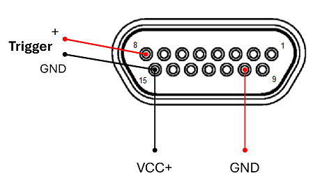
-
The cable with matching wire colors can be found on the Basler Website: I/O Cable micro-D15 open 1.83m
GPIO Setup#
After setting up the wiring, you must switch the frame grabber into the correct trigger mode, "single-ended". To do so, start the gpioTool command line tool. In a default installation, the gpioTool is located in the directory C:\Program Files\Basler\FramegrabberSDK\bin
Assuming you have only the Basler CXP-12 Interface Card installed in your system, start the gpioTool with the following command:
bin>_gpioTool.exe -b 0 -s 0:se,pu,ni
Info
With the command gpioTool.exe -b x -g, you can check the board and bank index with x = 0, 1, 2, etc.
pylon Settings#
Frame Grabber Settings#
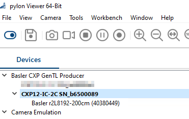
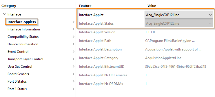
In the path Interface Applets, make sure the correct Interface Applet is selected:
Camera Settings#
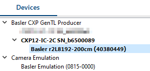
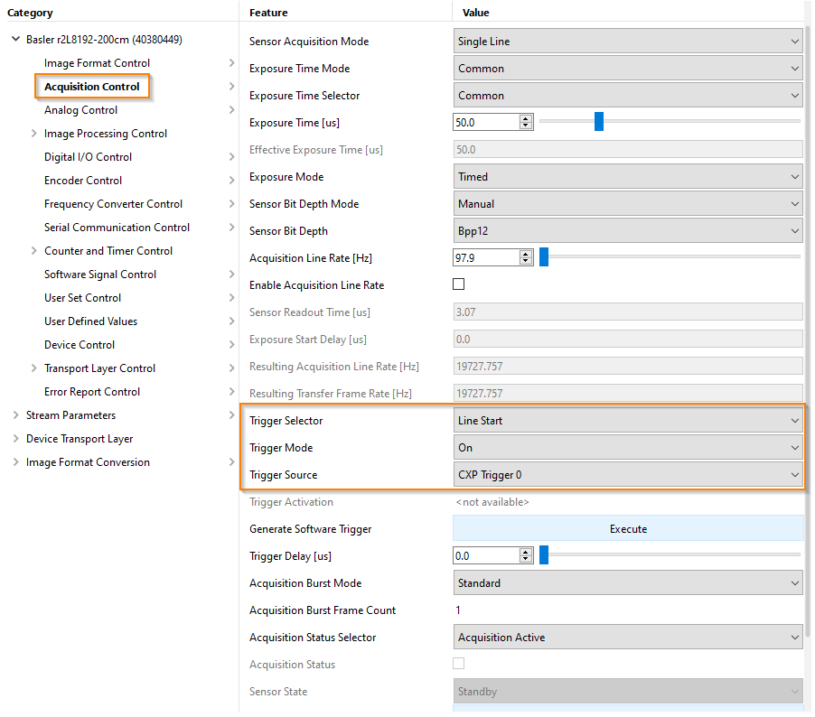
In the path Acquisition Control, activate the trigger:
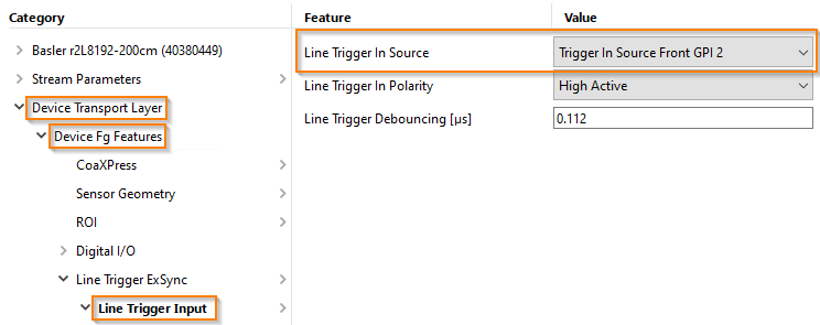
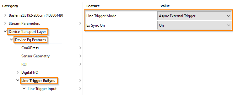
In the path Device Transport Layer → Device Fg Features:
- Set the Line Trigger Mode to Async External Trigger
- Set Ex Sync On to On
In the settings Line Trigger Input, select the required hardware trigger port. In this case, using pin 8 corresponds to Trigger In Source Front GPI 2
